Supercharge Your Innovation With Domain-Expert AI Agents!

Handle waterproof structure of electric tool

一种防水结构、电动工具的技术,应用在机动工具、制造工具、电路等方向,能够解决正反切换手柄防水结构没有考虑充分等问题,达到防水性能提高、提高防水性能的效果

Active Publication Date: 2011-04-13
MAKITA CORP
View PDF12 Cites 0 Cited by
  • Summary
  • Abstract
  • Description
  • Claims
  • Application Information

AI Technical Summary

Problems solved by technology

[0009] However, the prior art disclosed in these patent documents is carried out for the switch body, so the waterproof structure of the forward and reverse switching handle has not been fully considered.
The switch body is sealed by welding or bonding the switch boxes of the split structure with the on-off circuit inside, thus achieving a reliable waterproof and dustproof effect, but the forward and reverse switch operated by the switch handle The contact part of the circuit is exposed on the upper part of the switch body, so it needs to be reliably waterproofed

Method used


Image

  • Handle waterproof structure of electric tool
  • Handle waterproof structure of electric tool
  • Handle waterproof structure of electric tool

Examples


Embodiment Construction

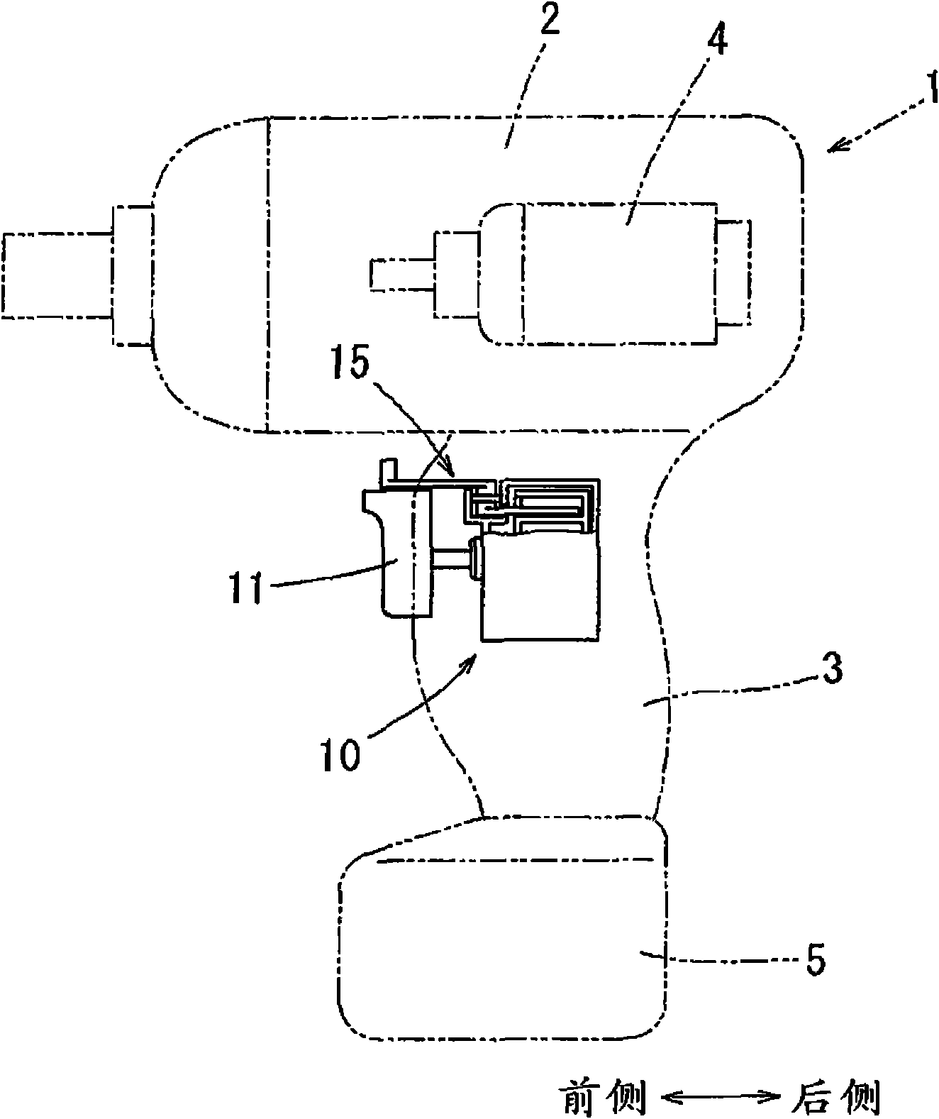
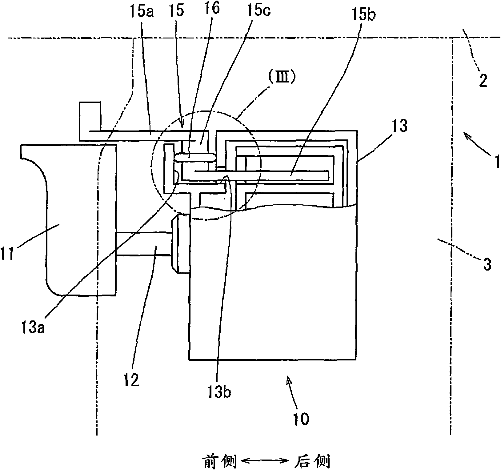
[0027] Below, according to Figure 1 to Figure 11 Embodiments of the present invention will be described. figure 1 The switch body 10 having the waterproof structure of the first embodiment and the electric screwdriver 1 having the switch body 10 are shown. The switch main body 10 is assembled in the handle part 3 of the electric screwdriver 1 . The handle portion 3 is provided in a state protruding laterally from the side portion of the tool body portion 2 . The switch body 10 is assembled near the bottom of the handle portion 3 (tool body portion side). A motor 4 as a drive source and a screw tightening mechanism (not shown) operated by the rotational power of the electric tool are incorporated in the tool main body 2 .

[0028] The switch body 10 has a switch handle 11 for switching on and off the power circuit of the motor 4 . The switch handle 11 is arranged in a state protruding from the front surface of the handle part 3 . When the user pulls the switch handle 11 w...


PUM


Abstract

The invention relates to a handle waterproof structure of an electirc tool, which improves the waterproof perfermance of the handle and solves the problem that the waterproof structure of a rotation supporting section of a normal / reverse switching handle of the electric screwdriver is not fully considered. A gasket (16) is installed on a rotation supporting section (15c) of the normal / reverse switching handle (15) to make it slidably contact with the inner surface of a supporting recess (13a), thus realizing water resistance; a groove section (20) is arranged on the rotation supporting section (15c); and the gasket (16) is embedded into the groove section (20) so as to form a labyrinth having a foreign body invasion path between the gasket (16) and the rotation supporting section (15c).

Description

technical field [0001] The present invention relates to, for example, a waterproof structure of a rotation support portion of a forward and reverse switching handle of a hand-held electric screwdriver. Background technique [0002] An electric screwdriver (electric screwdriver) includes: a tool body part in which a motor is incorporated; and a handle part protruding laterally from a side part of the tool body part. When the trigger-type switch handle at the bottom of the handle is pulled with fingertips, the closing button of the switch body assembled in the handle is pressed, so that the motor is started, and the front end of the tool body is installed on the The screwdriver bit on the spindle rotates in the screw tightening direction. In such a screw tightening machine, since the screw loosening operation is also performed, the main shaft can be rotated in the screw loosening direction by reversing the motor. [0003] Its structure is set as follows: On the switch body a...

Claims


Application Information

Patent Timeline
Patent Type & Authority Applications(China)
IPC IPC(8): B25F5/02B25B21/00
CPCB25F5/02H01H9/04H01H2009/048H01H21/08H01H9/06
Inventor 锦见淳一前川昌宏友永聪
Owner MAKITA CORP
Features
  • R&D
  • Intellectual Property
  • Life Sciences
  • Materials
  • Tech Scout
  • Unparalleled Data Quality
  • Higher Quality Content
  • 60% Fewer Hallucinations
Learn More