
Rotary shear mark tool rest of automatic wire stripper

A wire stripping machine and cutter technology, which can be used in circuit/collector parts, electrical components, equipment for dismantling/armored cables, etc.

Inactive Publication Date: 2013-02-20
浙江君权自动化设备有限公司
View PDF0 Cites 0 Cited by
  • Summary
  • Abstract
  • Description
  • Claims
  • Application Information

AI Technical Summary

Problems solved by technology

Through this setting, the invention is used as an accessory of the automatic wire stripping machine. When special cables such as coaxial cables need to be processed, the cutters are brought together by the cutter parallel mechanism, and the cutter is rotated in a circle by the cutter rotation mechanism. In this way, a complete circular cut that matches the cable outline is realized on the cable, which solves the traditional problem of wire sheath residue. After the invention completes the cutting process, the automatic wire stripping machine completes the automatic wire stripping process. Realize automatic stripping processing of special cables such as coaxial cables

Method used


Image

  • Rotary shear mark tool rest of automatic wire stripper
  • Rotary shear mark tool rest of automatic wire stripper
  • Rotary shear mark tool rest of automatic wire stripper

Examples


Embodiment Construction

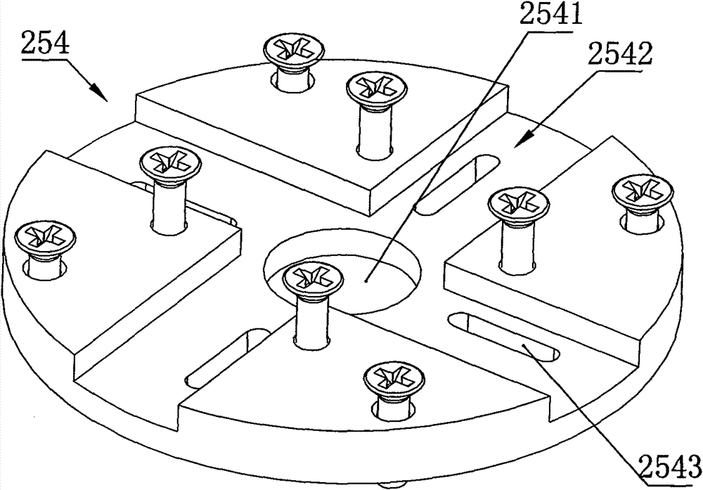
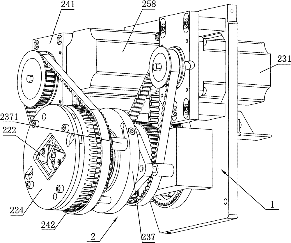
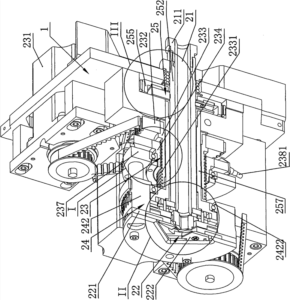
[0026] like Figure 1-3 The specific embodiment of the present invention shown includes a mounting frame 1, a knife rest assembly 2 installed on the mounting frame 1, and a motor assembly, and the knife rest assembly 2 includes a wire inlet pipe 21, a cutter assembly 22. The cutter combining mechanism 23 and the cutter rotating mechanism 24. The motor assembly includes a combining motor 231 adapted to drive the cutter combining mechanism 23 and a rotating motor adapted to drive the cutter rotating mechanism 24 241, the cutter rotation mechanism 24 includes a ring gear 242 that is driven and matched with the rotation motor 241, and the ring gear 242 is provided with a left and right through installation cavity 2421, and the cutter parallel mechanism 23 includes The transmission gear 232 that cooperates with the parallel knife motor 231 is provided with a threaded tube 233 that is fixedly interlocked with the transmission gear 232. The threaded tube 233 is provided with an exter...


PUM


Abstract

The invention discloses a rotary shear mark tool rest of an automatic wire stripper, which comprises a mounting rack, a tool rest assembly arranged on the mounting rack and a motor assembly, wherein the tool rest assembly comprises a wire inlet pipe, a cutter assembly, a cutter closing mechanism and a cutter rotating mechanism. The rotary shear mark tool rest has the advantages that: the rotary shear mark tool rest is used as an accessory of the automatic wire stripper; when special cables such as coaxial cables need processing, cutters are closed through the cutter closing mechanism, and meanwhile the cutters rotate on the circumference by using the cutter rotating mechanism, so that a complete circular shear mark matched with the outline of a cable is realized on the cable, and the traditional wire skin problem is solved; and after the shear mark process is finished, the automatic wire stripper finishes an automatic wire stripping process so as to realize full-automatic wire stripping of the special cables such as the coaxial cables.

Description

technical field [0001] The invention relates to an automatic wire stripping machine, in particular to a rotary cutting knife holder of the automatic wire stripping machine. Background technique [0002] In the existing automatic wire stripping machine, because the knife holders are all in the upper and lower knife setting structure, when the cable is stripped, the cutter cannot cut the cable sheath 360 degrees in a circle, and there is a problem of residual incision. Some coaxial cables or wires with shielding nets and wires with thin wires are stripped, and the upper and lower knife rests cannot solve the automatic peeling of such cables, and cannot meet the automation requirements of modern wire harness processing enterprises. Contents of the invention [0003] The purpose of the present invention is to overcome the shortcomings and deficiencies in the prior art, and provide a rotary cutting machine for automatic wire strippers that can improve the stripping quality of a...

Claims


Application Information

Patent Timeline
Patent Type & Authority Patents(China)
IPC IPC(8): H01R43/28H02G1/12
Inventor 倪君权
Owner 浙江君权自动化设备有限公司
Learn More