Method for compensating dead time of converter based on distortion function

A technology of dead time and compensation method, applied in the direction of converting AC power input to DC power output, output power conversion device, electrical components, etc., can solve the problem of reducing the steady-state output characteristics and performance of the converter, and determining the size of Ud , difficulties, etc., to achieve the effect of effective and simple algorithm, no disturbance, and reducing low-frequency harmonic components

Active Publication Date: 2011-04-13
WUXI SILENT ELECTRIC SYST SES TECH CO LTD +1
View PDF3 Cites 10 Cited by
  • Summary
  • Abstract
  • Description
  • Claims
  • Application Information

AI Technical Summary

Problems solved by technology

[0013] Diode conduction time T diode Determined by the device characteristics and the inductor current loop, T must be given correctly diode and then correctly give K dt is very diff

Method used


Image

  • Method for compensating dead time of converter based on distortion function
  • Method for compensating dead time of converter based on distortion function
  • Method for compensating dead time of converter based on distortion function

Examples


Embodiment Construction

[0037] Preferred embodiments of the present invention are described in detail as follows in conjunction with accompanying drawings:

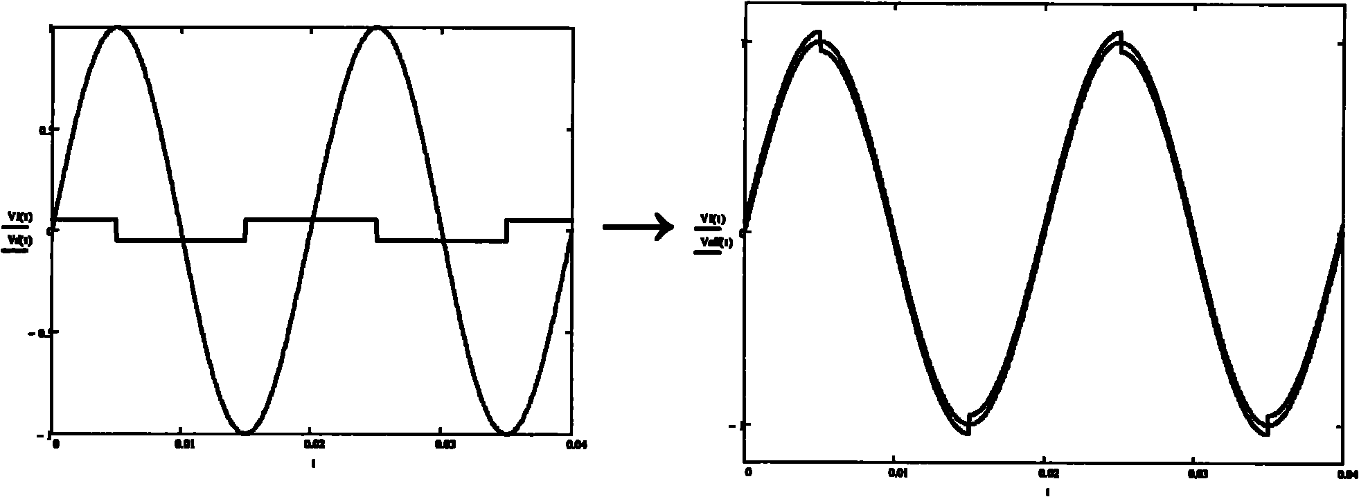
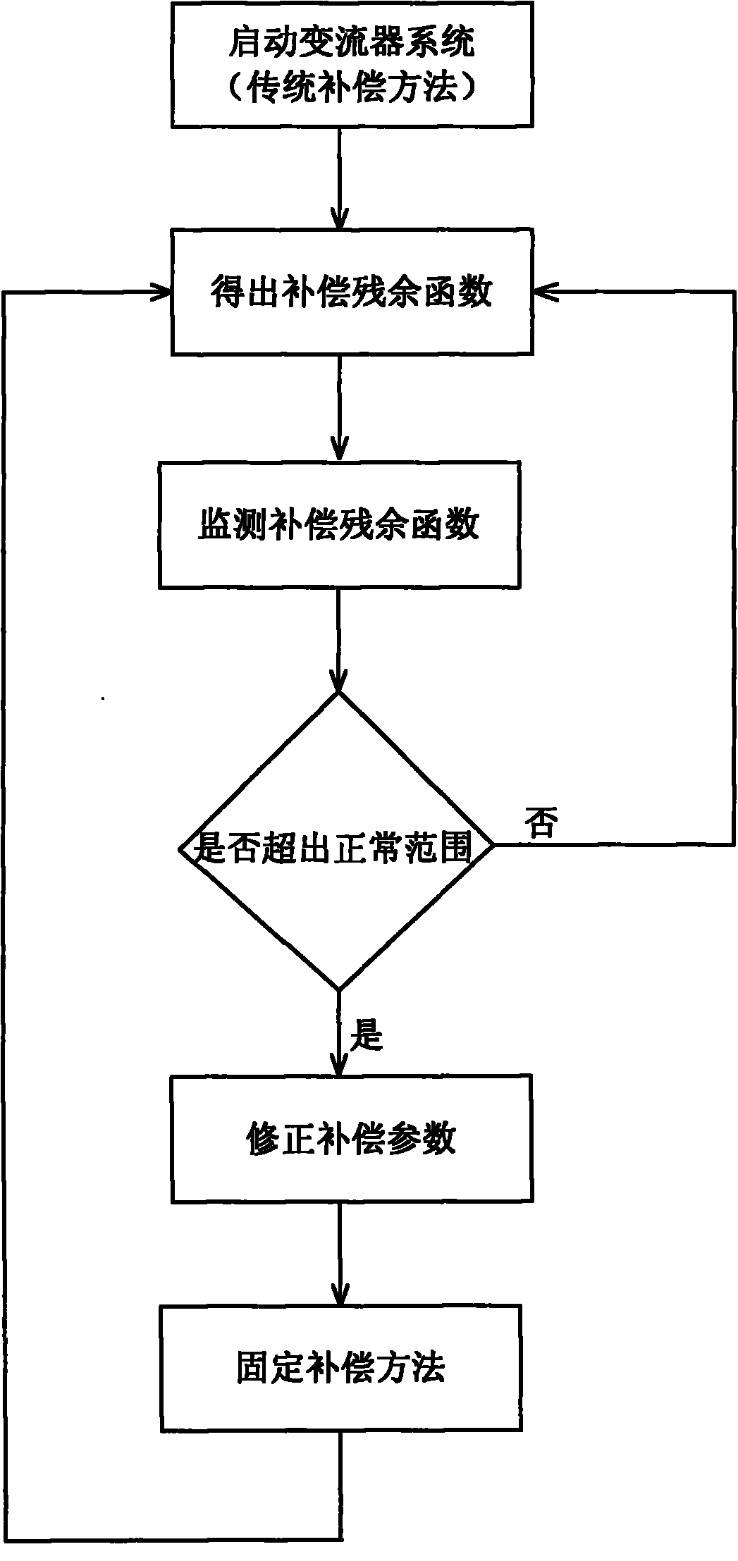
[0038] The implementation example of the present invention can be realized in a traditional converter vector control system. Such as Figure 5 As shown, this embodiment includes a dead time compensation module (3), the purpose of which is to compensate the dead time effect according to the distortion function; a compensation residual waveform calculation module (4), the purpose of which is to calculate The residual waveform formed by subtracting the sinusoidal vector output from the current transformer output under the condition; a distortion function correction module (5), which aims to adjust the distortion function online according to the compensated residual waveform. In actual operation, these three modules cooperate with traditional vector control and PWM output modules to run in a cycle.

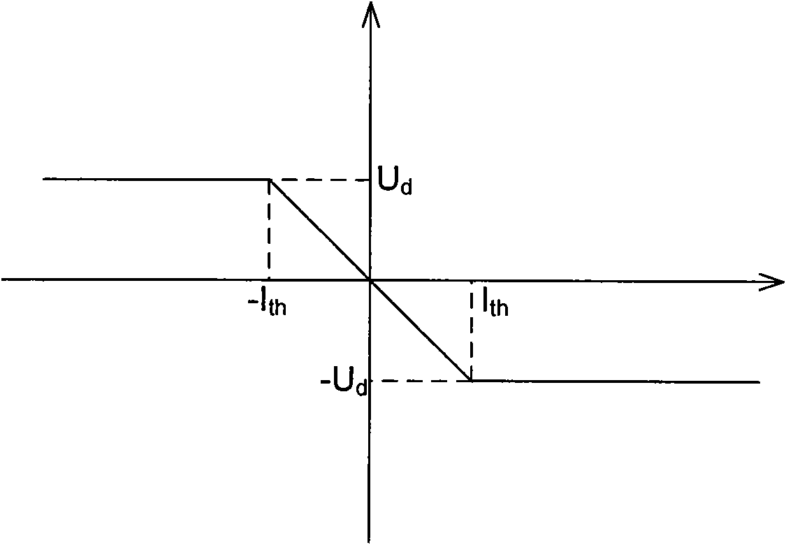
[0039] The dead time compensation module is bas...


PUM


Abstract

The invention discloses a novel method for compensating dead time of a converter, which is applied to universal voltage source converters. In the method, a distortion function correction step is increased on the basis of the normal method for compensating the dead time compensation. In the method, voltage feedback is used as a reference, and a dead time effect distortion function is corrected fora plurality of periods, so that the accuracy for dead time compensation can be effectively improved and the output quality of the converter is improved. The method is easy to implement and does not cause obvious disturbance to a converter control system.

Description

Technical field: [0001] The invention relates to a novel dead-time compensation method of a high-power converter, which can be applied to the drive output of any high-power converter including wind power converters and marine propulsion converters. The invention effectively compensates the linear error of the output of the converter caused by the dead time, improves the quality of the output waveform, and reduces the output torque fluctuation of the driving motor. Background technique: [0002] High-power converters have a broad application background and have become one of the core equipment in many industries. At present, the vast majority of high-power converters use a three-phase fully-controlled full-bridge circuit. In order to prevent the upper and lower devices (usually IGBTs) of the bridge circuit from being simultaneously turned on and short-circuited, the switching circuit will add dead time to the upper and lower devices of the bridge arm. During the switching p...

Claims


Application Information

Patent Timeline
IPC IPC(8): H02M7/5395H02M1/12
Inventor 乌云翔邵诗逸
Owner WUXI SILENT ELECTRIC SYST SES TECH CO LTD
Why Eureka
Try Eureka