Supercharge Your Innovation With Domain-Expert AI Agents!

Railway brake shoe

A brake shoe and main body technology, applied in the field of composite material railway brake shoes, can solve the problem of not being able to wait

Inactive Publication Date: 2015-05-13
RFPC HLDG CORP
View PDF9 Cites 0 Cited by
  • Summary
  • Abstract
  • Description
  • Claims
  • Application Information

AI Technical Summary

Problems solved by technology

As a result, it is difficult or impossible to benefit from metal inserts due to the lack of suitable means to support and hold them

Method used


Image

  • Railway brake shoe
  • Railway brake shoe
  • Railway brake shoe

Examples


Embodiment Construction

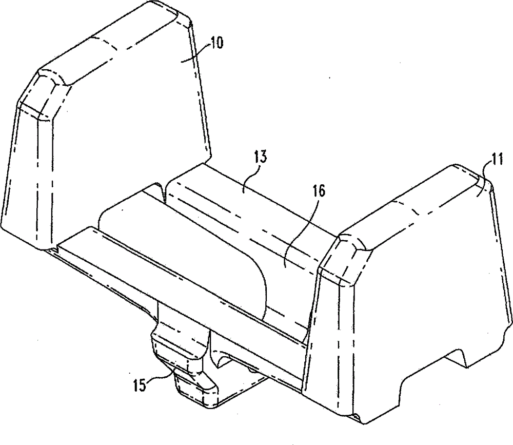
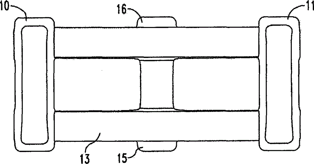
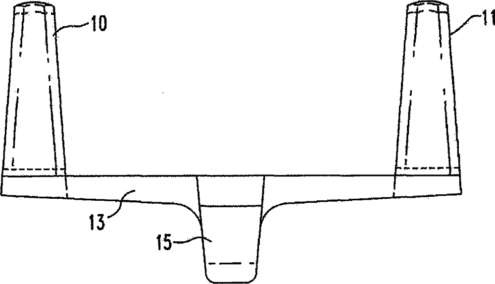
[0018] Refer below Figure 1 to Figure 4 , shows an insert for a brake shoe without a metal backing plate. The brake shoe is defined by a friction surface for applying pressure to the tread of the wheel and an opposing back surface arranged to contact and be secured to the brake shoe carrier. The metal insert 9 comprises two divided bodies 10, 11 having a friction face 12 on the friction surface of the brake shoe. The two separated bodies 10 , 11 extend away from the friction surface 12 .

[0019] A connecting portion 13 extends between the two spaced apart bodies 10 , 11 . The connecting portion 13 has a back face 14 disposed adjacent to the back surface of the brake shoe and providing support for the brake shoe holder. Two substantially parallel radially extending flanges 15 , 16 are integrally formed with the connecting portion 13 . The parallel flanges 15 , 16 are dimensioned to extend beyond the back surface of the brake shoe so as to define a keyway 17 .

[0020] Re...


PUM


Abstract

A brake shoe without a metal backing has a metal insert comprising two spaced apart bodies, a connecting portion having a back face adjacent to the back surface of the brake shoe, and two generally parallel radially extending flanges integral with the connecting portion. The parallel extensions define a keyway, wherein when the brake shoe is emplaced on the brake head, the keyway extends through an opening provided in the brake head.

Description

technical field [0001] The invention relates to the composite material railway brake shoe technology. Background technique [0002] The rail cars are supported and guided by steel wheels. Treads on the outer circumference of the wheel straddle the rails. Railcar brakes include brake shoes that frictionally engage the treads of the wheels. The brake shoe is supported by a brake shoe carrier which is movably supported by a brake transmission comprising a system of levers and cylinders. Brake shoes are made from a variety of materials, selected for their friction characteristics and effect on the wear life of the wheel tread. Many brake shoes are composites of materials with different properties. In a typical composite brake shoe, multiple materials with different frictional properties exert pressure on the wheel tread during braking. This can be achieved by inserting inserts made of different materials into the friction surface of the brake shoe, which consists of the mai...

Claims


Application Information

Patent Timeline
Patent Type & Authority Patents(China)
IPC IPC(8): F16D65/06
CPCF16D65/0037F16D65/062F16D2069/002
Inventor 约瑟夫·C·卡尔蒂莫西·A·朗夫
Owner RFPC HLDG CORP
Features
  • R&D
  • Intellectual Property
  • Life Sciences
  • Materials
  • Tech Scout
  • Unparalleled Data Quality
  • Higher Quality Content
  • 60% Fewer Hallucinations
Learn More