
Buffer device

A technology of buffer device and studio, applied in valve device, transportation and packaging, functional valve type, etc., to achieve the effect of improving ride comfort and restraining ride comfort

Inactive Publication Date: 2011-04-13
KYB CORP
View PDF3 Cites 9 Cited by
  • Summary
  • Abstract
  • Description
  • Claims
  • Application Information

AI Technical Summary

Problems solved by technology

[0013] Therefore, the present invention is made to improve the above disadvantages, and its object is to provide a shock absorber that can reduce the damping force and improve the ride comfort of the vehicle even when the piston speed is high.

Method used


Image

  • Buffer device
  • Buffer device
  • Buffer device

Examples


Embodiment Construction

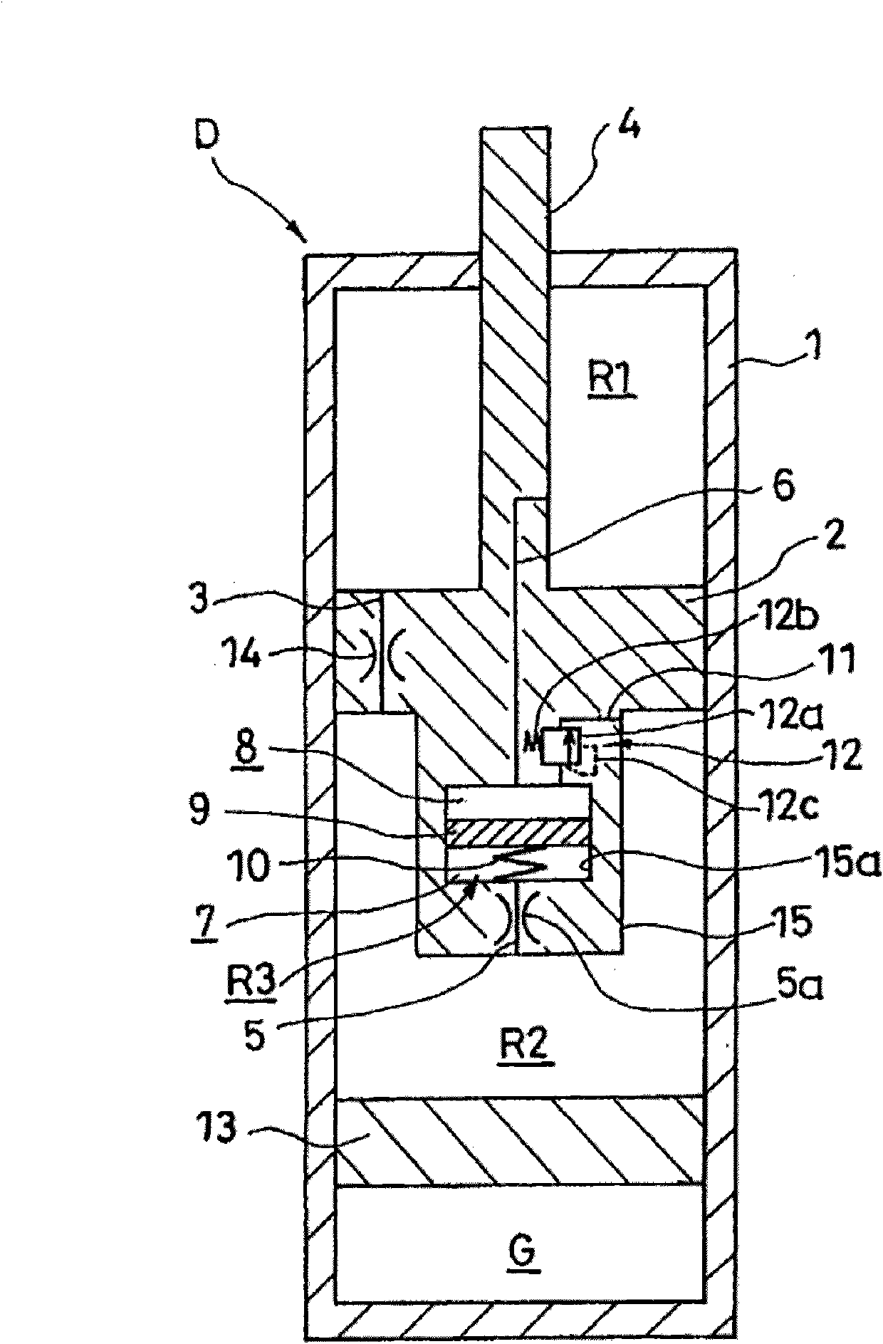
[0030] Hereinafter, the present invention will be described with reference to the drawings. Such as figure 1 As shown, the buffer device D of the present invention includes: a cylinder body 1; inserted into the cylinder body 1 in a manner that can slide freely in the cylinder body 1, and divides the cylinder body 1 into two working chambers, namely upper chamber R1 and The piston 2 as a partition wall member of the lower chamber R2; the passage 3 connecting the upper chamber R1 and the lower chamber R2; the pressure chamber R3; The pressure chamber R3 is divided into a chamber 7 communicating with the lower chamber R2 through one side flow path 5 and a free piston 9 communicating with another chamber 8 of the upper chamber R1 through the other side flow path 6; A spring element 10 generating a force due to the displacement of the pressure chamber R3; a detour passage 11 connecting the other chamber 8 with the lower chamber R2; and a relief valve 12 provided in the detour pas...


PUM


Abstract

A buffer device (D) is provided with: a cylinder (1); a partition wall member (2) slidably inserted within the cylinder (1) and partitioning the inside of the cylinder (1) into two operating chambers (R1, R2); a path (3) for interconnecting the two operating chambers (R1, R2); a pressure chamber (R3); a free piston (9) movably inserted within the pressure chamber (R3) and partitioning the pressure chamber (R3) into one chamber (7) connected to one of the operating chambers (R1, R2), which is the operating chamber (R2), through a flow path (5) on one side and into the other chamber (8) connected to the other operating chamber (R1) through a flow path (6) on the other side; and a spring element (10) for generating pressing force for minimizing displacement of the free piston (9) relative to the pressure chamber (R3). The buffer device is also provided with either or both of a bypass flow path (11) for interconnecting the other chamber (8) and said operating chamber (R2) and a bypass flow path for interconnecting said chamber (7) and the other operating chamber (R1), and a relief valve (12) is provided in the bypass flow path (11).

Description

technical field [0001] The invention relates to a buffer device. Background technique [0002] The buffer device described in JP2006-336816A and JP2007-78004A comprises: a cylinder body; a piston inserted into the cylinder body in a manner that can slide freely in the cylinder body, and divides the cylinder body into an upper chamber and a lower chamber; The first flow path on the top is used to connect the upper chamber and the lower chamber; the second flow path is opened from the front end of the piston rod to the side to connect the upper chamber and the lower chamber; Pressure chamber, housing installed at the front end of the piston rod; free piston inserted into the pressure chamber in a manner that can slide freely in the pressure chamber, dividing the pressure chamber into one chamber and another chamber; screw for applying force to the free piston Therefore, one chamber in the pressure chamber communicates with the lower chamber through the second flow path, and t...

Claims


Application Information

Patent Timeline
Patent Type & Authority Applications(China)
IPC IPC(8): F16F9/34B60G17/08F16F9/32F16K17/04
CPCF16F9/5126F16F9/516
Inventor 寺冈崇志政村辰也
Owner KYB CORP
Learn More