Oil supply device of sewing machine

An oil supply device, sewing machine technology, applied in sewing machine components, sewing equipment, lubrication/cooling devices, etc., can solve the problems of easy oil leakage, increased cost, large size, etc., and achieve the effect of preventing wear and tear and preventing melting

Inactive Publication Date: 2011-04-20
PEGASUS SEWING MACHINE MFG
View PDF5 Cites 0 Cited by
  • Summary
  • Abstract
  • Description
  • Claims
  • Application Information

AI Technical Summary

Problems solved by technology

[0006] However, in the prior art disclosed in Document 1, since the oil supply to the second airtight chamber is carried out by receiving and guiding the lubricating oil scattered in the first airtight chamber in a barrel shape by the oil supply pipe, the oil supply The amount of oil is unstable due to individual differences in sewing machines or differences in rotational speed (speed).
Therefore, in order to prevent the needle bar from being melted or worn out, the amount of oil supplied to the second airtight chamber has to be set larger than the actually required amount. The outside of the oil discharge mechanism is additionally set
In order to solve the above-mentioned problems, for example, in the case of connecting from the discharge port of the trochoid pump to the aforementioned oil supply pipe by using a pipe or the like, the oil supply amount of the trochoid pump is very large in order to supply oil to the inside of the entire sewing machine. Large, it is extremely difficult to introduce the desired trace amount of lubricating oil into the second airtight chamber
[0007] If the prior art disclosed in Document 2 is applied, a necessary amount of lubricating oil can be supplied to the second airtight chamber. However, the oil supply device disclosed in Document 2 is complicated and bulky, which leads to increased costs and cannot accommodate the inside of the sewing machine. The problem

Method used


Image

  • Oil supply device of sewing machine
  • Oil supply device of sewing machine
  • Oil supply device of sewing machine

Examples


Embodiment Construction

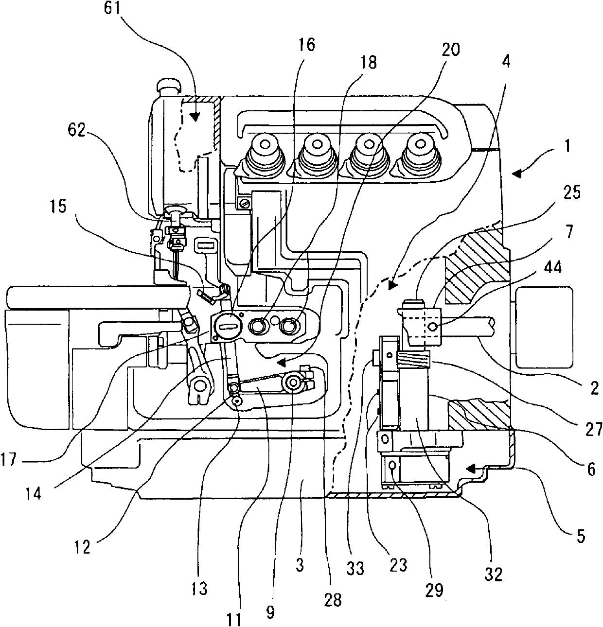
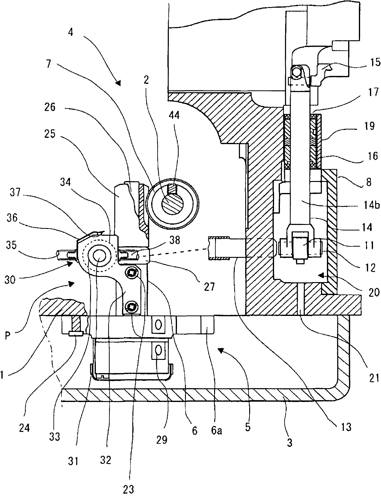
[0056] Hereinafter, embodiments of the present invention will be described based on the drawings. figure 1 It is a front view showing a partially cutaway overlock sewing machine to which the present invention is applied. figure 2 is seen from the left side figure 1 Partial sectional view of the main part of the oil supply device of the sewing machine. In addition, in figure 1 In , the cover 8 provided on the front surface of the second airtight chamber 20 is omitted to show its internal mechanism.

[0057] In the first airtight chamber 4 communicated with the oil pocket 3 and formed in the frame 1 , the main shaft 2 is horizontally arranged and rotatably supported by the frame 1 . In front of the frame 1 , a second airtight chamber 20 is provided in connection with the first airtight chamber 4 , and the front surface of the second airtight chamber 20 is covered with a cover 8 . The main shaft 2 is connected to the upper looper shaft 9 via a known upper looper driving mech...


PUM


Abstract

The invention provides an oil supply device of a sewing machine, which is simple in structure and is capable of being mounted in the sewing machine and stably supplying required lubricating oil in small amount to a second sealing chamber. The oil supply device comprises a first sealing chamber (4), and a second pump (30) is adjacently arranged to a first pump (5). The second pump (30) comprises an oil accommodating chamber (60) capable of containing lubricating oil, an oil guiding hole (46) which is capable of guiding the lubricating oil in the oil accommodating chamber (60), an oil spraying hole (50) which is capable of discharging the lubricating oil to the oil accommodating chamber (60), and a pin (37) linked to the first pump (5) with one end entering and withdrawing the oil accommodating chamber (60). The lubricating oil can be guided in from the oil guiding hole (46) and be discharged from the oil spraying hole (50) through the volume change in the oil accommodating chamber (50) due to the entering and withdrawing of the pin (37) in the oil accommodating chamber (60). The lubricating oil discharged from the oil spraying hole (50) is supplied to the second sealing chamber (20).

Description

technical field [0001] The present invention relates to a sewing machine oil supply device, and more specifically, to a sewing machine oil supply device for supplying lubricating oil to a part of a member protruding from a sewing machine frame and sliding. Background technique [0002] In order to prevent oil leakage from members such as the needle bar of the overlock sewing machine and the upper looper table, a part of which protrudes and slides from the frame of the sewing machine, in the prior art, it is known to have a first oil pocket in the frame. The airtight chamber is a structure that is distinguished from the second airtight chamber that accommodates the base of the above-mentioned member (for example, refer to Document 1). Document 1 applies the above prior art to the needle bar mechanism of an overlock sewing machine. A trochoidal pump is installed in a first airtight chamber integrally formed with a base constituting a part of the frame and equipped with an oil ...

Claims


Application Information

Patent Timeline
IPC IPC(8): D05B71/00
Inventor 川上淳司
Owner PEGASUS SEWING MACHINE MFG
Why Eureka
Try Eureka