Anti-loosening terminal block and terminal assembly

A connection terminal and anti-loosening technology, which is applied in the direction of connection, electrical components, conductive connection, etc., can solve the problems of cumbersome procedures, inconvenient installation, and increased manufacturing costs, and achieve the effects of convenient maintenance, convenient installation, and prevention of electrical accidents

Active Publication Date: 2013-03-13
ZHEJIANG PEOPLE ELE APPLIANCE
View PDF0 Cites 2 Cited by
  • Summary
  • Abstract
  • Description
  • Claims
  • Application Information

AI Technical Summary

Problems solved by technology

[0002] The terminals of low-voltage electrical equipment such as traditional AC contactors mostly use screws and arched gaskets to fix the connecting wires. Due to the poor shock resistance of screw fixing, they are easy to loosen, and the screws and gaskets are easy to fall off when connecting. falling, prone to electrical accidents
In order to prevent the screws from falling and loosening, there are currently connecting terminals that use plug-in connection wires, and there are also guide grooves on the insulating parts of the terminals and springs installed on the conductive sheets to prevent the screws from falling. The spring makes the structure of the conductive sheet particularly complicated, and also increases the manufacturing cost. For the plug-in connection terminal of the wire, the plug-in piece must be fixed on the terminal of the wire before connecting, which is very inconvenient to install.
[0003] Traditional low-voltage electrical appliances are provided with accommodating grooves in the insulating shell, and terminal terminals are arranged in the accommodating grooves. This structure integrates the accommodating grooves for setting the connecting terminals and the housing, and only needs one mold for injection molding. It has the advantage of a relatively simplified structure, but there are also some disadvantages: for example, when the terminal is installed in the accommodating groove, and when it needs to be replaced and maintained, the process is relatively cumbersome

Method used


Image

  • Anti-loosening terminal block and terminal assembly
  • Anti-loosening terminal block and terminal assembly
  • Anti-loosening terminal block and terminal assembly

Examples


Embodiment 1

[0034] (Embodiment 1, anti-off terminal)

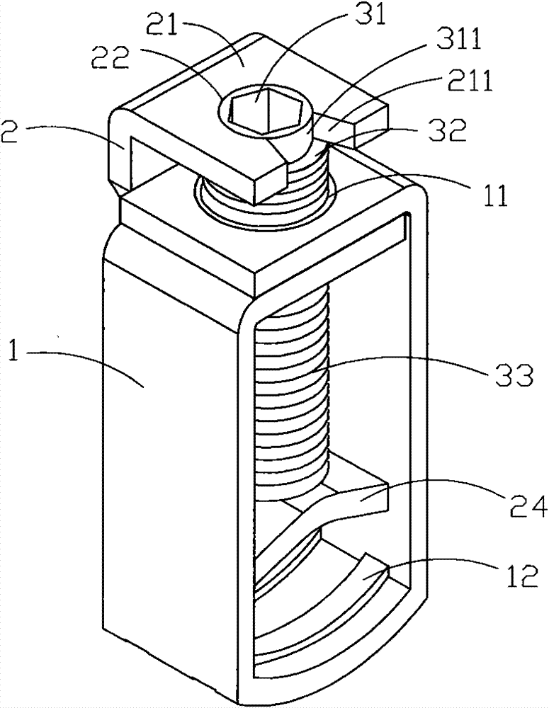
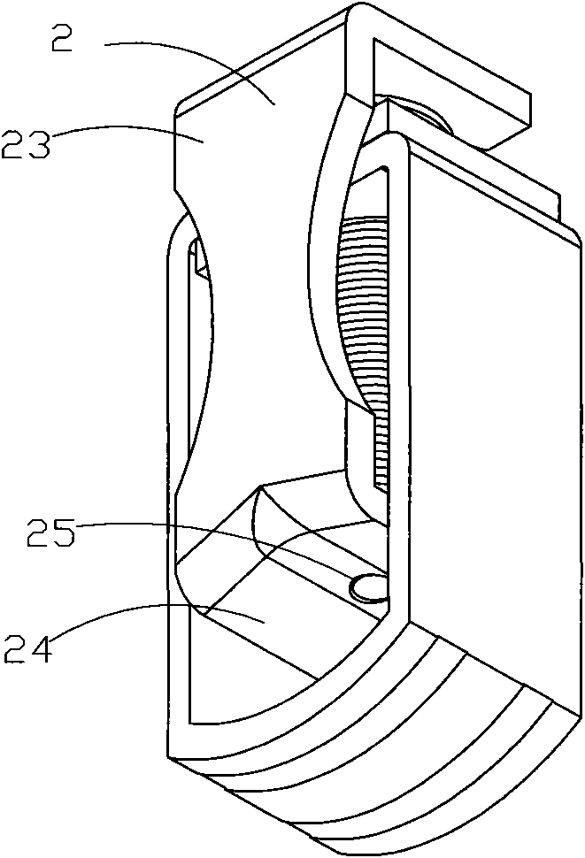
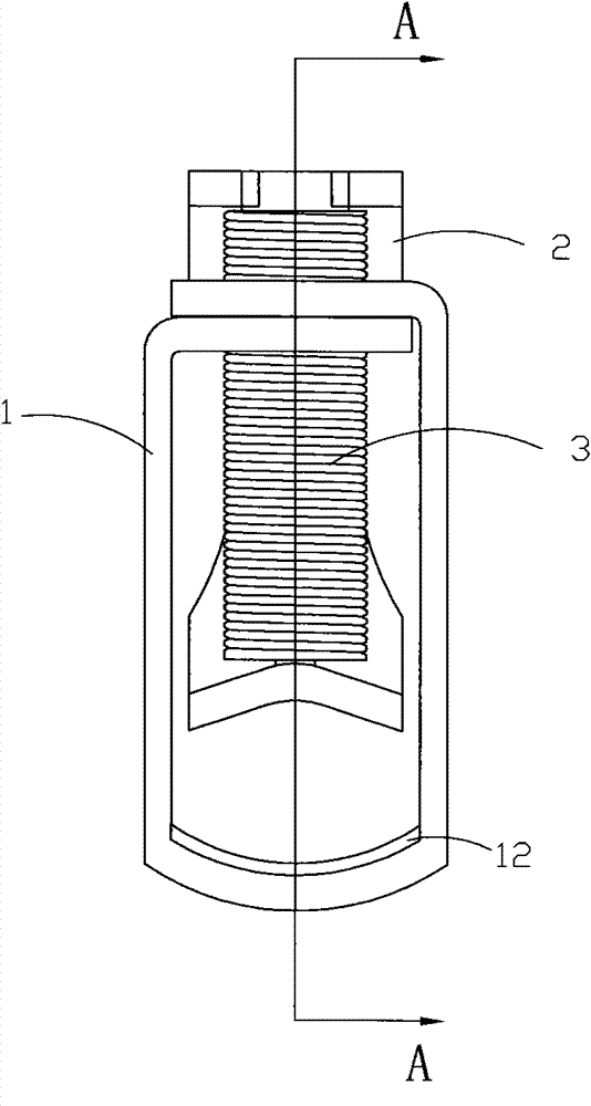
[0035] Figure 1 to Figure 4 A specific embodiment of the anti-off terminal in the present invention is shown, wherein figure 1 It is a three-dimensional schematic diagram of a structure of the anti-off terminal in the present invention; figure 2 yes figure 1 A schematic diagram of a three-dimensional structure of the anti-off terminal when viewed from another angle; image 3 yes figure 1 The front view of the anti-slip terminal block shown; Figure 4 yes image 3 The cross-sectional view of the anti-loosening terminal shown along the line A-A.

[0036] This embodiment is an anti-off terminal, see Figure 1 to Figure 4, including a metal frame 1 with through holes in the front and rear, a wire pressing piece 2 and an adjusting bolt; the top of the metal frame 1 is provided with a screw hole 11, and the adjusting bolt can rotate back and forth in the screw hole 11; it is characterized in that : The adjusting bolt 3 is sequenti...

Embodiment 2

[0038] (Embodiment 2, wiring assembly)

[0039] Figure 5 to Figure 8 A specific embodiment of the wiring assembly in the present invention is shown, wherein Figure 5 It is a schematic diagram of a three-dimensional structure of the wiring assembly in the present invention; Figure 6 yes Figure 5 A schematic diagram of the three-dimensional structure of the wiring assembly shown when viewed from another angle; Figure 7 yes Figure 5 Cross-sectional view of the wiring assembly shown, taken through the middle, Figure 8 yes Figure 5 A three-dimensional structural schematic diagram of the wiring assembly shown in the contactor.

[0040] This embodiment is a wiring assembly using the anti-off terminal in Embodiment 1, see Figure 5 to Figure 7 , compared with Embodiment 1, it also includes an insulating terminal block 4, and the terminal block is provided with at least one accommodating cavity 41 for setting an anti-off terminal; the top wall of the accommodating cavity...


PUM


Abstract

The invention discloses an anti-loosening terminal block and a terminal assembly. The terminal block comprises a metal frame, a line pressing piece and an adjusting bolt, wherein the top end of the metal frame is provided with a screw hole; the adjusting bolt is successively provided with a fastening part, an anti-loosening part, a thread part and a crimping part; the line pressing piece is successively provided with a spacing zone, a connection zone and a crimping zone, wherein the spacing zone is provided with a spacing hole; the upper part of the adjusting bolt is positioned in the spacing hole of the crimping part; the anti-loosening part of the adjusting bolt is abutted against the spacing zone of the crimping part; and the crimping part is abutted on the crimping zone of the crimping part. The terminal assembly comprises an insulated wire holder and the above anti-loosening terminal block, wherein the insulated wire holder is provided with a containing cavity; the top wall of the containing cavity is provided with a fastening thorough hole; the bottom wall of the containing cavity is provided with an installation port; the front wall and the rear wall of the containing cavity are provided with wiring holes; the fastening through hole of the containing cavity rightly faces to the fastening part of the adjusting bolt; and the wiring hole of the containing cavity just faces to the metal frame. The terminal block has good anti-loosening effect and convenient installation, and the terminal assembly is convenient to install and overhaul.

Description

technical field [0001] The invention belongs to the technical field of structural design of low-voltage electrical appliance terminals, and in particular relates to an anti-dropping terminal and a terminal assembly. Background technique [0002] The terminals of low-voltage electrical equipment such as traditional AC contactors mostly use screws and arched gaskets to fix the connecting wires. Due to the poor shock resistance of screw fixing, they are easy to loosen, and the screws and gaskets are easy to fall off when connecting. fall, prone to electrical accidents. In order to prevent the screws from falling and loosening, there are currently connecting terminals that use plug-in connection wires, and there are also guide grooves on the insulating parts of the terminals and springs installed on the conductive sheets to prevent the screws from falling. The spring makes the structure of the conductive sheet particularly complicated, and also increases the manufacturing cost....

Claims


Application Information

Patent Timeline
Patent Type & Authority Patents(China)
IPC IPC(8): H01R9/00H01R9/16H01R9/24H01R4/40
Inventor 黄章武包志舟钱永勤赵青青杨辉胡云霞
Owner ZHEJIANG PEOPLE ELE APPLIANCE
Why Eureka
Try Eureka