Connector

A connector and side connection technology, applied in the direction of connection, contact part, coupling device, etc., can solve problems such as access interruption, and achieve the effect of preventing instantaneous interruption, preventing twisting, and good contact state

Inactive Publication Date: 2011-04-20
SMK CO LTD
View PDF4 Cites 2 Cited by
  • Summary
  • Abstract
  • Description
  • Claims
  • Application Information

AI Technical Summary

Problems solved by technology

At this time, problems such as access being forcibly interrupted may occur even though the card is installed.

Method used


Image

  • Connector
  • Connector
  • Connector

Examples


Embodiment 1

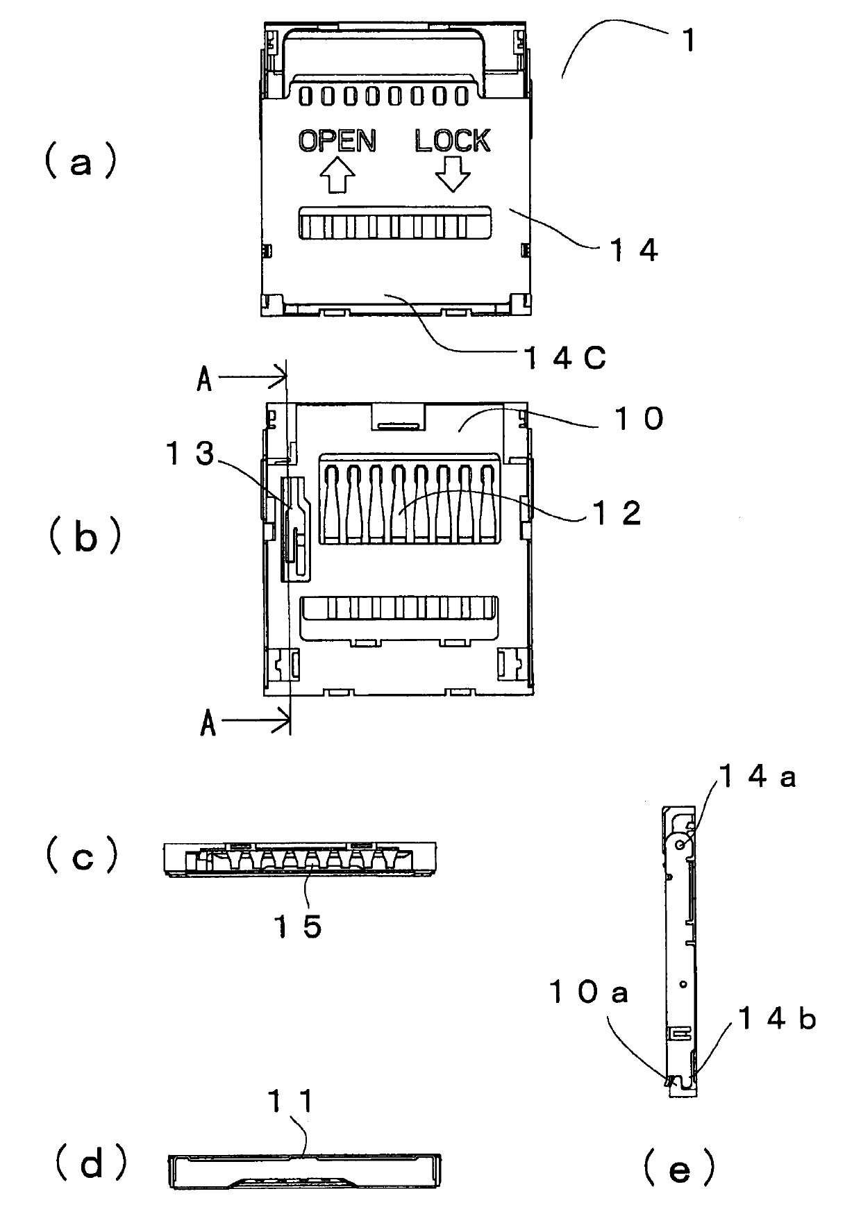
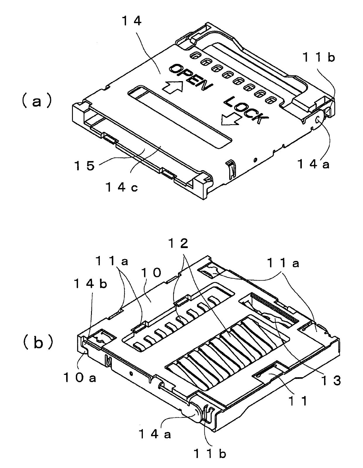
[0077] First, based on Figure 1 to Figure 7 The configuration of the first embodiment will be described.

[0078] The connector 1 of this embodiment includes: a housing 10, which is made of insulating resin, includes a mounting hole 15 for accommodating the card 2, and holds the board 11 by integral molding; contacts 12, 12, ... , is embedded in the housing 10 with integral molding, and is respectively connected with a plurality of electrodes 21, 21, ... of the installed card-type electronic storage medium 2 through its own elastic force; Install for testing. The housing 10 further includes a protective cover 14 that engages with a bearing portion 11b that is a part of the plate 11 at one end on the plane side so as to rotate around the shaft 14a and move freely in parallel. figure 1 Between the protective cover 14 in such a closed state and the housing 10 is an attachment hole 15 capable of accommodating the card 2 .

[0079] The contact 12 faces the mounting hole 15 in a...

Embodiment 2

[0095] As a second embodiment, configurations different from those of the above-mentioned first embodiment will be described below, and redundant descriptions will be omitted.

[0096] The second embodiment, which is different from the first embodiment, is characterized in that the second electrode 42 of the card detection circuit 4 that detects the installation of the card 2 of the connector 1 is not provided on the card 2, but is applied to the substrate of the first elastic contact portion 13da. The portion where the force portion 13da2 faces is provided.

[0097] Since the structures of the connector and the switch contact 13 are the same as those disclosed in the first embodiment, descriptions are made below for the state of use.

[0098] The card 2 placed in the mounting hole 15 first biases the contact portion 13db1 of the second elastic contact portion 13db downward with its own weight, and the card 2 is further displaced downward by the closed protective cover 14 . A...

Embodiment 3

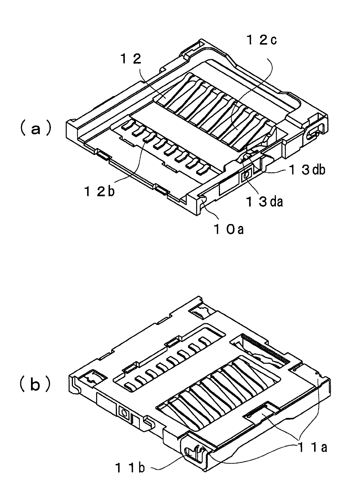
[0102] Next, a third embodiment will be described.

[0103] The structure different from the first embodiment is as Figure 8 As shown, there is no assembly portion 13b of the switch contact 13, and the switch electrode 22 located on the card 2 is provided as the first electrode 41 of the card detection circuit 4, and the switch contact 13 is provided at a position facing the substrate biasing portion 13da2. There is a second electrode 42 .

[0104]When the card 2 is installed, in the card 2 clamped between the protective cover 14 and the contact 12, each electrode 21 is suitably in elastic contact with the contact 12 to be in a connected state, and is connected to the first electrode 41 provided on the card 2. The switch contact 13 of the card 2 is elastically contacted with the switch electrode 22 of the card 2 as the first electrode of the detection circuit 4 of the card 2, so that the card detection circuit 4 is closed through the switch contact 13, and the installation o...


PUM


Abstract

The invention relates to a connector having a contact member with a transient interruption prevention mechanism. The contact member of the connector (1) comprises a fixing part (12a) kept in a housing (10), and a first and a second elastic contacting part (12da, 12db) having at least two shunts and are connected to the fixing part (12a). The first elastic contacting part (12da) comprises a contacting part (12da1) which protrudes from an installing hole (15), applies force and is connected to the electrode (21) of an installed opposite side connection body (2), and a substrate force application part (12da1) which applies force to a substrate (3) through the displacement of the contacting part of the installed opposite side connection body (2). In the second elastic contacting part (12db), the contacting part (12da1) protrudes from the installing hole (15), applies force and is connected to the electrode (21) of the installed opposite side connection body (2). Even if the contacting part (12db1) with the force being applied by the installed opposite side connection body (2) conducts displacement, the front end is a free end.

Description

technical field [0001] The present invention mainly relates to a contact structure for stabilizing electrical contact of contacts of electrical connectors such as switch terminals. Background technique [0002] Historically, to sense the installation of a card connector, switch contacts that work with the installed card and are free to sense the circuit of the card are used. One end of the switch contact is fixed to the case, and the other end is arranged so as to be in elastic contact with the fixed terminal. [0003] For example, in Japanese Patent Application Laid-Open No. 2006-324043, the movable terminal 4 is arranged to face the fixed terminal fixed to the case at a predetermined interval. [0004] Patent Document 1: Japanese Patent Laid-Open No. 2006-324043 [0005] However, in the above case, since the movable terminal is in one-point contact with the cantilever spring, resonance occurs when a vibration or impact with the same natural frequency as the movable termi...

Claims


Application Information

Patent Timeline
Patent Type & Authority Applications(China)
IPC IPC(8): H01R12/71H01R13/02
Inventor 江尻孝一郎
Owner SMK CO LTD
Why Eureka
Try Eureka