Radially-adjustable heavy-duty cutting layer milling cutter

An adjustable and heavy-duty technology, applied in the direction of milling cutting blades, milling cutters, milling machine equipment, etc., can solve the problems of affecting processing efficiency, long processing cycle, and cutting teeth cannot all participate in cutting, so as to improve surface processing quality and improve cutting Edge strength and the effect of improving the metal removal rate

Inactive Publication Date: 2015-08-19
HARBIN UNIV OF SCI & TECH
View PDF7 Cites 20 Cited by
  • Summary
  • Abstract
  • Description
  • Claims
  • Application Information

AI Technical Summary

Problems solved by technology

At present, the domestic water chamber head has not been formed and forged. It can only be forged into a similar cylinder and then cut. The amount of material removal is large (up to about 70%), and it is mainly milling. The processing cycle is long and the efficiency is high. very low
At present, the face milling cutter is used to mill the head of the water chamber, but the blank is a forging, the forging surface is uneven, and there are many surface defects (cracks, slag inclusions, forging shovel grooves and pits, scale, hard and Brittle network carbide, etc.), poor machinability, rough machining or rough machining, it is easy to cause the blade to be damaged due to impact; the cutting depth changes during the milling process, resulting in the cutter teeth not being able to fully participate in the cutting, resulting in milling cutter Low utilization rate affects processing efficiency
At the same time, the periodic cutting force generated in the milling process makes the machining prone to vibration, and even reaches the natural frequency of the tool to cause chatter

Method used


Image

  • Radially-adjustable heavy-duty cutting layer milling cutter
  • Radially-adjustable heavy-duty cutting layer milling cutter
  • Radially-adjustable heavy-duty cutting layer milling cutter

Examples


specific Embodiment approach 1

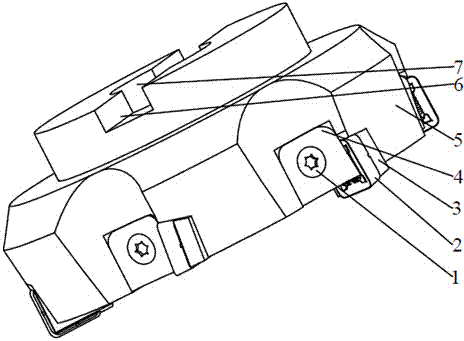
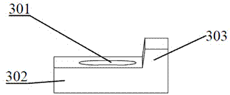
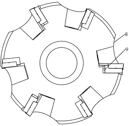
[0035] Specific implementation mode one: as Figure 1-Figure 7 As shown, a radially adjustable heavy-duty layer cutting milling cutter, the unequal-angle cutter body 5 of the cutter is connected with the main shaft of the machine tool through the center hole 7, and the keyway 6 is used to connect with the main shaft of the machine tool and transmit torque. The blade mounting grooves 11 of the cutter are arranged at different distances on the outer wall of the cutter body to increase the natural frequency of the cutter body, change the period of the milling force, suppress the vibration during milling, reduce the probability of cutter damage and improve the surface processing quality. The teeth of the milling cutter adopt a stepped distribution design, and a 3mm-high step block 12 is provided in the blade installation groove 11 of the unequal angle cutter body 5, and 6 blades 2 are installed on the unequal angle cutter body 5, and the blades 2 become Unequal angle distribution,...

specific Embodiment approach 2

[0036] Specific implementation mode two: combination figure 1 , Image 6 Explain that in this embodiment, the main and secondary cutting edges of the blade 2 have a structural design to strengthen the strength of the cutting edge, improve the strength of the cutting edge, and can shunt chips at the same time, and a spherical shape is provided near the main and negative cutting edges. The protrusion reduces the wear of the tip and improves the service life of the blade.

specific Embodiment approach 3

[0037] Specific implementation mode three: combination figure 1 , Figure 4Note that when the layer cutting milling cutter in this embodiment cuts the head of the water chamber, the diameter of the layer cutting milling cutter is 125 mm, the cutter adopts 75° and 90° entering angles, and the layer cutting milling cutter adopts 90° entering angle, During milling, the main and auxiliary cutting edges of the tool participate in the cutting at the same time, which improves the utilization rate of the tool and thus improves the processing efficiency. If a machine tool with a smaller power is used, a 75° lead angle can be used to reduce the axial force. The undisclosed technical features in this embodiment are the same as those in the first embodiment.


PUM

PropertyMeasurementUnit
heightaaaaaaaaaa

Abstract

The invention discloses a radially-adjustable heavy-duty cutting layer milling cutter applicable to the field of heavy-type milling processing, and aims to solve the problems that during heavy-duty milling water chamber end enclosing, surfaces of workblanks are uneven, multi-defective and poor in machinability; cutting blades are prone to being damaged by impacts during rough machining or hogging machining; during milling, cutting depth changes frequently, which results in that not all cutter teeth are involved in cutting, utilization rate of the milling cutter is low, the cutting layer milling cutter of a fixed radial stepped structure is short in service life, machining efficiency is influenced and the like. Cutter teeth of the cutting layer milling cutter are designed in a stepped distribution, by means of increasing cutting depth, metal removal rate is increased, and machining efficiency is improved; by the aid of a radial adjusting mechanism, the cutting blades in an upper layer are enabled to move radially, a proper overhang amount can be selected, and strength of the cutting blades is enhanced. A radially-adjustable cutter pad is positioned by a pad block, auxiliary time including cutter amounting time, cutter adjusting time and the like is saved; up-warp chip holding grooves are formed in a cutter body in design, the depths of the positions, close to the cutting blades, of the chip holding grooves are far larger than that of the positions, distant from the cutting blades, of the chip holding grooves, up-warp slopes are formed in the chip holding grooves, and when cutting chips flow in the chip holding grooves, the chips can be separated from the cutter body quickly, friction between the chips and the cutter body is reduced, and service life of the cutter body is prolonged.

Description

technical field [0001] The invention belongs to the technical field of cutting tools for heavy-duty cutting, and in particular relates to a radially adjustable heavy-duty cutting layer cutting milling cutter. Background technique [0002] The water chamber head of the AP1000 evaporator of the nuclear power nuclear island is a key part of the third-generation nuclear power plant equipment. Its material is SA508Ⅲ steel, which is difficult to manufacture. Due to the harsh working environment of the nuclear reactor, the head of the water chamber needs to work under high temperature and high radiation for a long time. In order to ensure safety, the head of the water chamber is required to be very precise and must be integrally forged. At present, the domestic water chamber head has not been formed and forged. It can only be forged into a similar cylinder and then cut. The amount of material removal is large (up to about 70%), and it is mainly milling. The processing cycle is lon...

Claims


Application Information

Patent Timeline
Patent Type & Authority Applications(China)
IPC IPC(8): B23C5/00B23C5/24B23C5/26
CPCB23C5/08B23C5/26B23C2210/205B23C2200/28B23C2200/323B23C2200/326B23C2200/126B23C2200/088B23C2200/081B23C5/24B23C5/2278
Inventor 程耀楠韩禹卢真真陈涛
Owner HARBIN UNIV OF SCI & TECH
Why Eureka
Try Eureka