Turbine wheel in an exhaust gas turbine of an exhaust gas turbocharger

a technology of exhaust gas turbine and turbine wheel, which is applied in the direction of liquid fuel engine components, wind motors with parallel air flow, wind motors with perpendicular air flow, etc., can solve the problems of increasing the load of the turbine wheel, and achieve the effect of high turbine efficiency levels, sufficient stability, and low moment of mass inertia

Inactive Publication Date: 2010-09-21
DAIMLER AG
View PDF4 Cites 19 Cited by
  • Summary
  • Abstract
  • Description
  • Claims
  • Application Information

AI Technical Summary

Benefits of technology

[0008]The turbine wheel blades are constructed in such a way that the ratio of the hub contour thickness to the external contour thickness of each turbine wheel blade, at least for the axial half of the turbine wheel which is adjacent to the turbine wheel outlet, is greater than or if appropriate also equal to the value 8 so that the hub contour thickness is at least eight times larger than the external contour thickness. This thickness ratio for the turbine wheel blades ensures that each blade is made relatively thick in the region of the turbine wheel hub and is made relatively thin in the region of its external contour. The fact that, with the design according to the invention, the blades are relatively thin in the region of the external contour meets requirements for high turbine efficiency levels. The moment of mass inertia is kept comparatively low, which enhances a rapid increase or change in the turbine rotational speed and at the same time a super-proportional increase in power of the exhaust gas turbine in the transient mode. The fact that the hub area is at the same time constructed with relatively thick walls ensures sufficient stability even at the increased turbine rotated speeds.
[0009]Since increasing the charger speed by, for example, 10% already leads to an increase in the engine braking power of approximately 30%, measures for increasing the rotational speed of the exhaust gas turbocharger leads to a super-proportional increase in the engine braking power levels. The inventive configuration of the turbine wheel blades, in particular as a result of the comparatively thick-walled construction in the region of the wheel hub, results in a significant increase in the first natural frequency of the turbine wheel, as a result of which a sufficient distance from the resonant speed can be maintained even at raised charger speeds. The risk of the blades fracturing is thus considerably reduced.
[0012]According to a further expedient embodiment there is provision for the axial end wall, adjacent to the turbine wheel inlet, of the turbine wheel to extend radially up to the greatest external diameter of the turbine wheel blades. This greater radial extent of the end wall or rear wall of the turbine wheel compared to the prior art enables efficiency advantages of over 2% to be obtained, possibly even up to over 5% in the case of dual-flow asymmetrical turbine housings since false flows and undesired eddying are reduced or even completely eliminated. In order to keep the increase in mass inertia and rigidity of the wall in the external wheel region low, the axial thickness of the end wall is expediently selected to be less than 1% of the greatest external diameter of the turbine wheel blades.

Problems solved by technology

Using a variable turbine geometry in the exhaust gas turbine leads to increased loading of the turbine wheel since high speed compression surges can occur in particular when there is a variable turbine geometry between adjacent guide blades in the choked position, and said surges can impact on the turbine wheel.

Method used


Image

  • Turbine wheel in an exhaust gas turbine of an exhaust gas turbocharger
  • Turbine wheel in an exhaust gas turbine of an exhaust gas turbocharger
  • Turbine wheel in an exhaust gas turbine of an exhaust gas turbocharger

Examples


Embodiment Construction

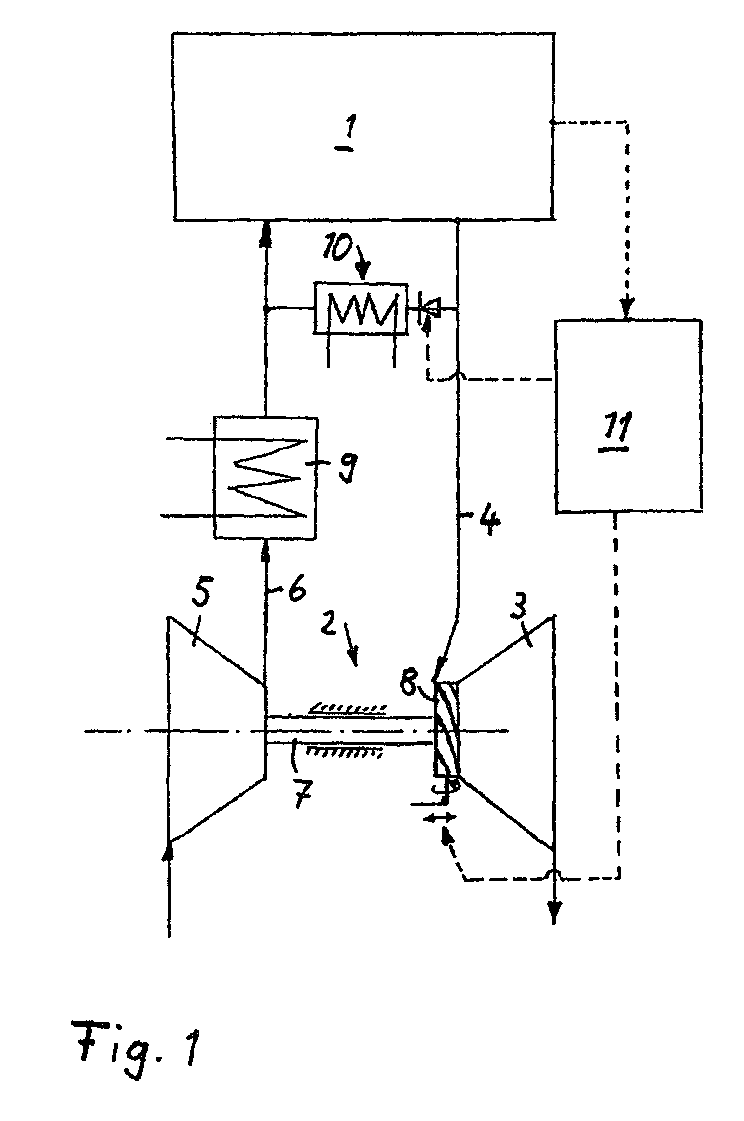
[0017]The internal combustion engine 1 illustrated in FIG. 1—a diesel internal combustion engine or a spark ignition engine—is a supercharged engine with an exhaust gas turbocharger 2 which comprises an exhaust gas turbine 3 in the exhaust section 4 of the internal combustion engine and a compressor 5 in the intake section 6. The turbine wheel of the exhaust gas turbine 3 and the compressor wheel of the compressor 5 are rotationally coupled by means of a shaft 7. In the fired drive operating mode of the internal combustion engine the exhaust gases which are expelled from the engine under pressure drive the turbine wheel, the rotational movement of which is transmitted via the shaft 7 to the compressor wheel, as a result of which ambient air is sucked in and compressed to a raised charge pressure. In order to improve the supercharging, the exhaust gas turbine 3 is equipped with a variable turbine geometry 8 which is constructed in particular as a guide grating ring in the turbine inl...


PUM


Abstract

In a turbine wheel of an exhaust gas turbine comprising a turbine wheel with a hub and a plurality of turbine wheel blades which are arranged on the turbine wheel hub and which extend axially between a turbine wheel inlet and a turbine wheel outlet, the turbine wheel blades are constructed in such a way that the ratio of the hub contour thickness to the external contour thickness of each turbine wheel blade follows a defined function.

Description

[0001]This is a Continuation-In-Part Application of pending international patent application PCT / EP2005 / 006286 filed Jun. 11, 2005 and claiming the priority of German patent application 10 2004 029 830.0 filed Jun. 19, 2004.BACKGROUND OF THE INVENTION[0002]The invention relates to a turbine wheel in an exhaust gas turbine of an exhaust gas turbocharger with a wheel hub and a plurality of blades arranged on the wheel hub and extending axially between the turbine inlet and the turbine outlet.[0003]The document DE 102 12 032 A1 discloses an exhaust gas turbocharger for an internal combustion engine, composed of a compressor in the intake section of the internal combustion engine and an exhaust gas turbine in the exhaust section, said turbine being driven by the pressurized exhaust gases, the rotational movement being transmitted to the compressor wheel which subsequently compresses ambient air to a raised charge pressure which is fed to the cylinders of the internal combustion engine. ...

Claims


Application Information

Patent Timeline
Patent Type & Authority Patents(United States)
IPC IPC(8): F01D5/14F01DF01D5/04F01D5/16F02C6/12
CPCF01D5/048F01D5/141F01D5/16F02C6/12F05D2220/40Y10S416/02Y10S416/05
Inventor SUMSER, SIEGFRIEDSCHMID, WOLFRAM
Owner DAIMLER AG
Why Eureka
Try Eureka