Dual-control steam cleaner

A cleaner and dual-control technology, applied in pump control, cleaning methods and utensils, cleaning methods using liquids, etc., can solve problems such as unsatisfactory cleaning effect, easy to burn users or others, insufficient steam pressure and temperature, etc. , to achieve the effect of safe use, convenient operation, steam pressure and temperature increase

Inactive Publication Date: 2011-04-27
梁金然
View PDF5 Cites 2 Cited by
  • Summary
  • Abstract
  • Description
  • Claims
  • Application Information

AI Technical Summary

Problems solved by technology

The steam cleaner with this structure has the following defects: 1. When the push-type control member 06 is pressed by hand, the water pump 03 directly pumps water into the steam generator 04, and at the same time, the steam is immediately ejected from the nozzle 05 until All the steam in the steam generator 04 has been released
So once the water pump 03 pumps too much water, even if the push-type control member 06 is released, the steam will continue to spray out, which is easy to burn the user or others, and is easily mistaken for releasing the push-type control member 06. stop steaming
2. If there is water remaining in the steam generating device 04 after the previous use, the steam will be ejected from the nozzle 05 automatically when the next use is made, even if the push-type control part 06 is not touched, which may cause burns user or others
3. Because when the push-type control part 06 is pressed by hand, the steam will be ejected from the nozzle 05 immediately, so the pressure and temperature of the steam are not high enough, and the cleaning effect is not ideal

Method used


Image

  • Dual-control steam cleaner
  • Dual-control steam cleaner
  • Dual-control steam cleaner

Examples


Embodiment Construction

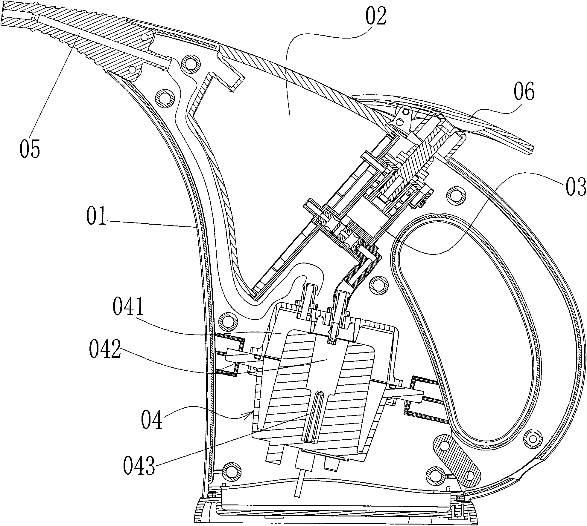
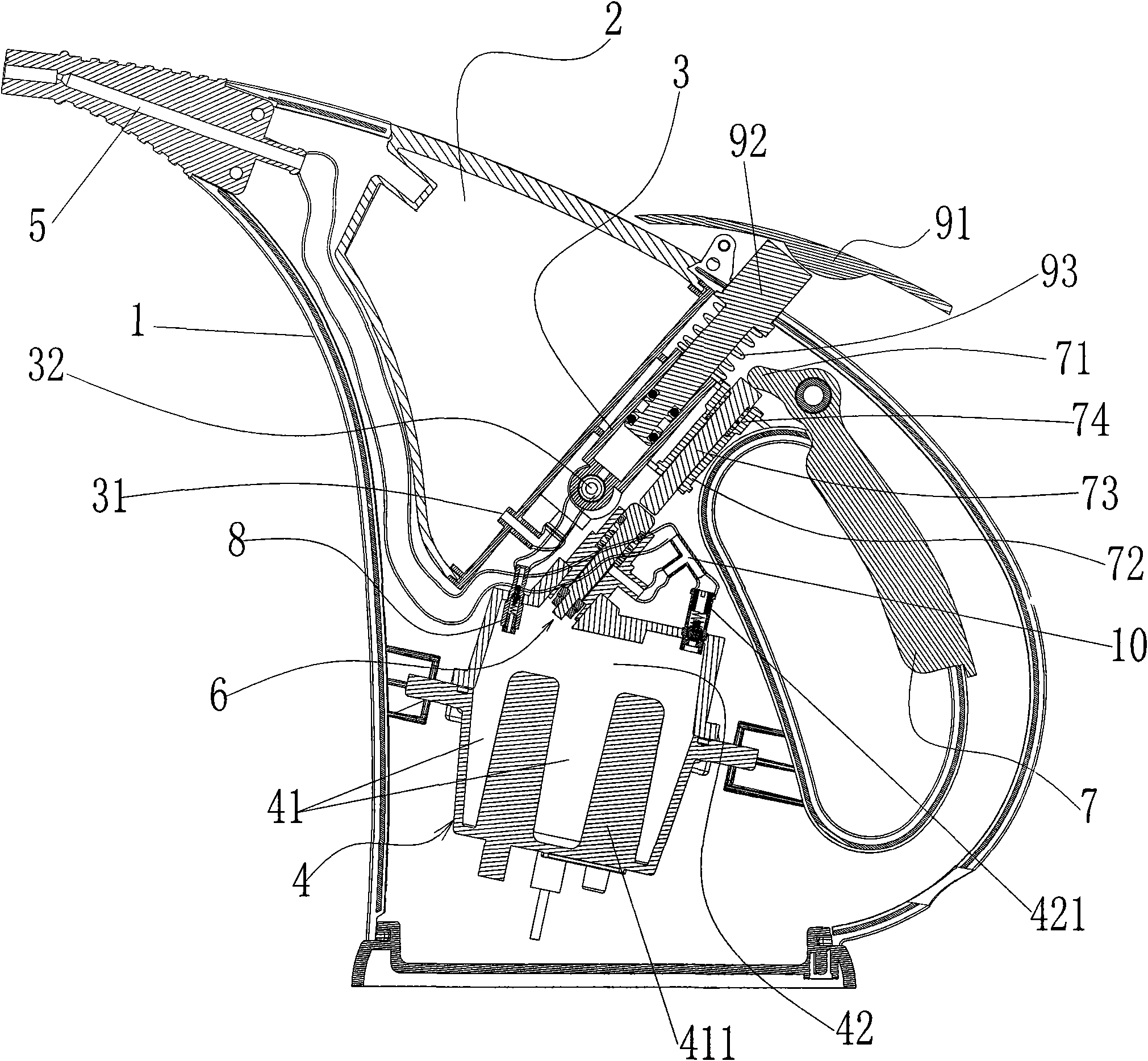
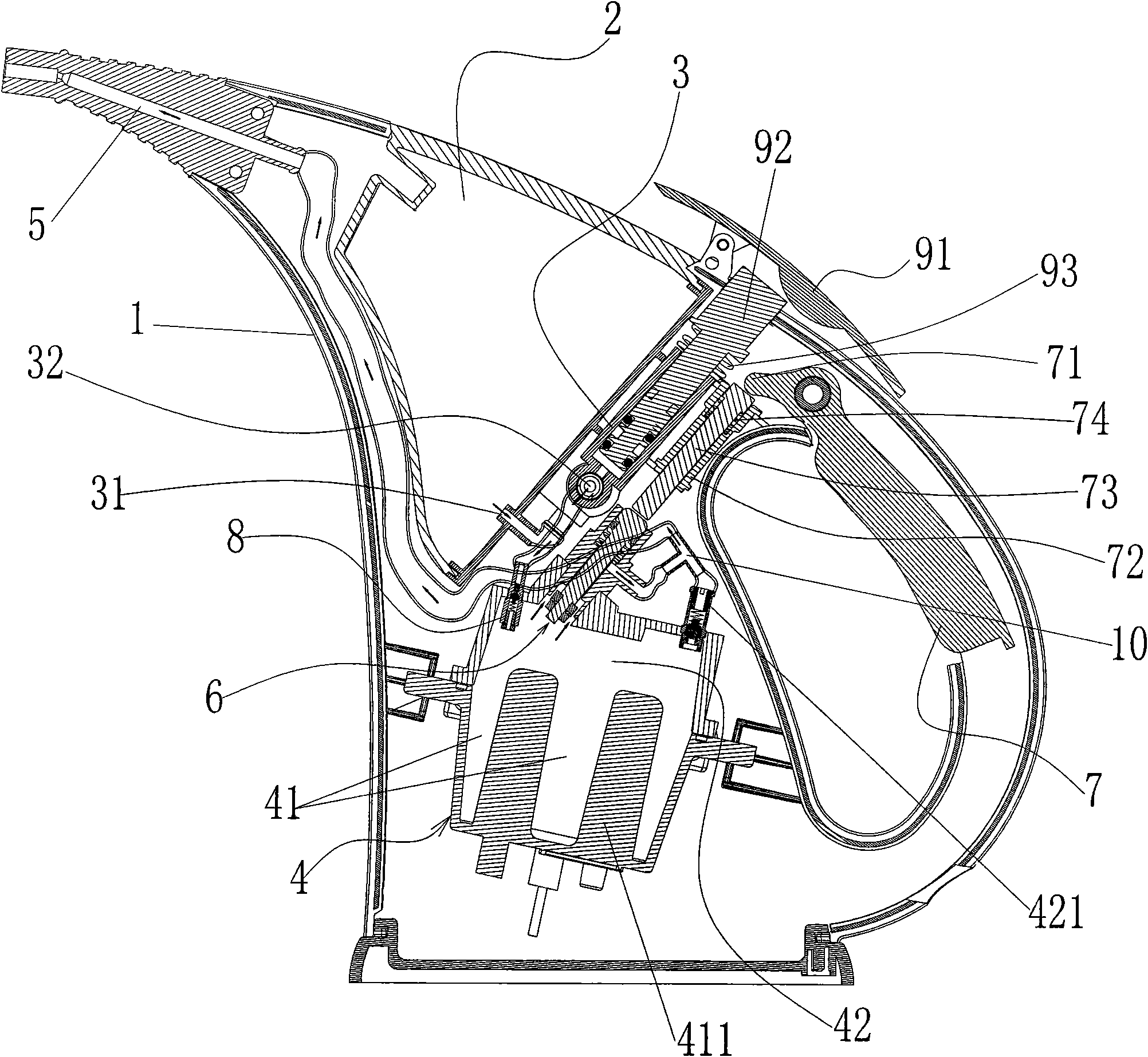
[0023] Such as Figure 2 to Figure 10 As shown, a dual-control steam cleaner includes a housing 1 with a handle, a water tank 2 disposed in the housing, a water pump 3, a push-type water pump control member, a steam generating device 4, a nozzle 5, and a nozzle 5 and a steam The steam sealing valve 6 between the generating devices 4, and a steam sealing valve control member which can open or close the steam sealing valve is arranged at the handle of the housing.

[0024] The water tank 2 is used to hold water or cleaning liquid; the water pump 3 includes a water pump cylinder, the water pump cylinder is provided with a water inlet 31 and a water outlet 32, and the water inlet 31 is connected to the water tank 2; A heating chamber 41, a steam chamber 42 located above the heating chamber 41, and a water inlet 8 connected to the heating chamber 41 are provided. The heating chamber 41 is provided with a heating element 411, and the water inlet 8 is provided with a valve core 81 an...


PUM


Abstract

The invention relates to a dual-control steam cleaner which comprises a shell with a handle, wherein a water tank, a water pump, a steam generating device, a nozzle and a push type water pump control member are arranged in the shell, the water pump is provided with a water inlet and a water outlet, the water inlet is connected with the water tank, the steam generating device is internally provided with a heating cavity and a steam cavity positioned above the heating cavity, a heating body is arranged in the heating cavity, the water outlet of the water pump is connected with the steam generating device, the nozzle is connected with the steam cavity, and the push type water pump control member can control the water pump to pump water or cleaning solution in the water tank into the heating cavity. The dual-control steam cleaner is characterized in that a steam closing valve is arranged between the nozzle and the steam cavity, and the shell is provided with a steam closing valve control member capable of opening or closing the steam closing valve. The invention has the advantages that the water pump and the steam closing valve are respectively independently controlled, thus the steam cleaner is safer in use; when the handle of the steam cleaner is held, the opening / closing control of the steam closing valve can be realized, thus the steam cleaner is more convenient for operation; and the steam generating device can generate higher-pressure and higher-temperature steam, thus the cleaning effect is better.

Description

Technical field: [0001] The present invention relates to a dual control steam cleaner. Background technique: [0002] The existing steam cleaner includes a housing 01, a water tank 02 disposed in the housing 01, a water pump 03, a steam generating device 04, a nozzle 05 and a push-type control member 06, and the water tank 02 is used to hold water or cleaning liquid , the water pump 03 has a water inlet and a water outlet, the water inlet is connected to the water tank 02, a steam chamber 041, a heating chamber 042 and a heating element 043 arranged in the heating chamber are arranged in the steam generating device 04, and the heating chamber 042 is provided with a steam flow hole communicating with the steam chamber 041, the water outlet of the water pump 03 is connected to the heating chamber 042, the nozzle 05 is connected to the steam chamber 041, and the push-type control member 06 can control the water pump 03 to The water or cleaning liquid in the water tank 02 is pu...

Claims


Application Information

Patent Timeline
Patent Type & Authority Applications(China)
IPC IPC(8): B08B3/02F04B49/00
Inventor 周建国罗增祥
Owner 梁金然
Why Eureka
Try Eureka