Convexity modifying method for ball track
A bearing raceway and raceway technology, which is applied in the field of crown modification of bearing raceways, can solve the problems of inability to realize bearing raceway surface machining, limited processing range, complex structure, etc., so as to shorten the production cycle and improve the contact Fatigue performance, the effect of improving machining quality
- Summary
- Abstract
- Description
- Claims
- Application Information
AI Technical Summary
Problems solved by technology
Method used
Image
Examples
Embodiment 1
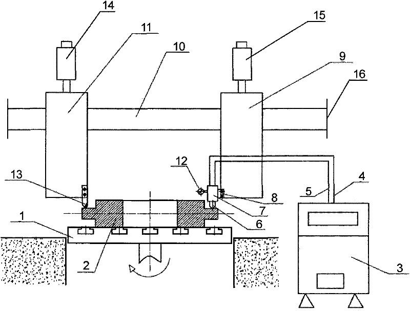
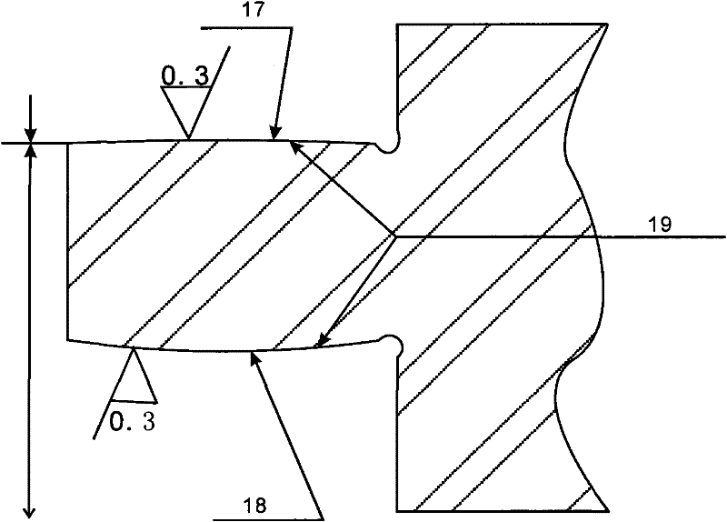
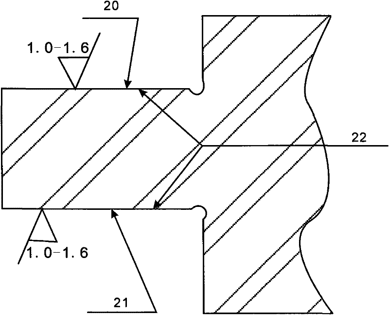
[0040] A method for modifying the convexity of a bearing raceway. The bearing body manufactured in advance is machined out of the required raceway surface with a lathe, and then heat treated. The bearing body formed with the raceway surface and heat-treated is placed on an ultrasonic On the control cabinet, carry out at least one convexity modification on the raceway surface at the same time as finishing the raceway surface, the steps are as follows:
[0041] Step 1. Machining the prefabricated bearing body to the required raceway surface with a lathe;
[0042] Step 2, heat-treating the bearing body forming the raceway at 820°C;
[0043] Step 3. Set the heat-treated bearing body on the ultrasonic control cabinet with the finishing device and the repairing device, set the linear speed of the workpiece to 80-110m / min, the cutting amount of the finishing device and the cutting speed of the vibrating tool head The amount is 0.1 ~ 0.25mm / r, and the amount of convexity of the racew...
Embodiment 2
[0046] A method for modifying the crown of a bearing raceway, the steps are as follows:
[0047] Step 1. Machining the prefabricated bearing body to the required raceway surface with a lathe;
[0048] Step 2, heat-treating the bearing body forming the raceway at 830°C;
[0049] Step 3. Set the heat-treated bearing body on the ultrasonic control cabinet with the finishing device and the repairing device, set the linear speed of the workpiece to 80-110m / min, the cutting amount of the finishing device and the cutting speed of the vibrating tool head The amount is 0.1~0.25mm / r, and the convexity modification amount of the raceway is set to 10μm-30μm;
[0050] Step 4: Turn on the ultrasonic numerical control device, and the finish turning tool holder set at one end of the CNC lathe drives the turning tool to perform finish turning on the bearing raceway. The trimming device on the frame is pressed against the finished bearing raceway surface under the force of the pressing device...
Embodiment 3
[0052] A method for modifying the crown of a bearing raceway, the steps are as follows:
[0053] Step 1. Machining the prefabricated bearing body to the required raceway surface with a lathe;
[0054] Step 2, heat-treating the bearing body forming the raceway at 840°C;
[0055] Step 3. Set the heat-treated bearing body on the ultrasonic control cabinet with the finishing device and the repairing device, set the linear speed of the workpiece to 80-110m / min, the cutting amount of the finishing device and the cutting speed of the vibrating tool head The amount is 0.1 ~ 0.25mm / r, and the amount of convexity of the raceway is set to 10μm-30μm;
[0056]Step 4: Turn on the ultrasonic numerical control device, and the finish turning tool holder set at one end of the CNC lathe drives the turning tool to perform finish turning on the bearing raceway. The trimming device on the frame is pressed against the finished bearing raceway surface under the force of the pressing device. The com...
PUM
| Property | Measurement | Unit |
|---|---|---|
| surface roughness | aaaaa | aaaaa |
| surface roughness | aaaaa | aaaaa |
Abstract
Description
Claims
Application Information
 - R&D
- Intellectual Property
- Life Sciences
- Materials
- Tech Scout
- Unparalleled Data Quality
- Higher Quality Content
- 60% Fewer Hallucinations
Browse by: Latest US Patents, China's latest patents, Technical Efficacy Thesaurus, Application Domain, Technology Topic, Popular Technical Reports.
© 2025 PatSnap. All rights reserved.Legal|Privacy policy|Modern Slavery Act Transparency Statement|Sitemap|About US| Contact US: help@patsnap.com


