

Tooth-pressing device
A technology of hydraulic pump and main body, which is used in the joining of wooden veneers, wood processing appliances, nailing tools, etc., can solve the problems of uneven nailing of metal plates, poor connection effect, time-consuming, etc. smoothing effect
Inactive Publication Date: 2011-04-27
CHENGDU CANYA WOOD IND
View PDF7 Cites 1 Cited by
- Summary
- Abstract
- Description
- Claims
- Application Information
AI Technical Summary
Problems solved by technology
Manual operation is time-consuming, and it will cause uneven nailing of the metal plate, and the connection effect is not good
Method used
View moreImage
Smart ImageViewing Examples

Examples
Embodiment Construction
[0011] The present invention will be further described below in conjunction with the accompanying drawings.
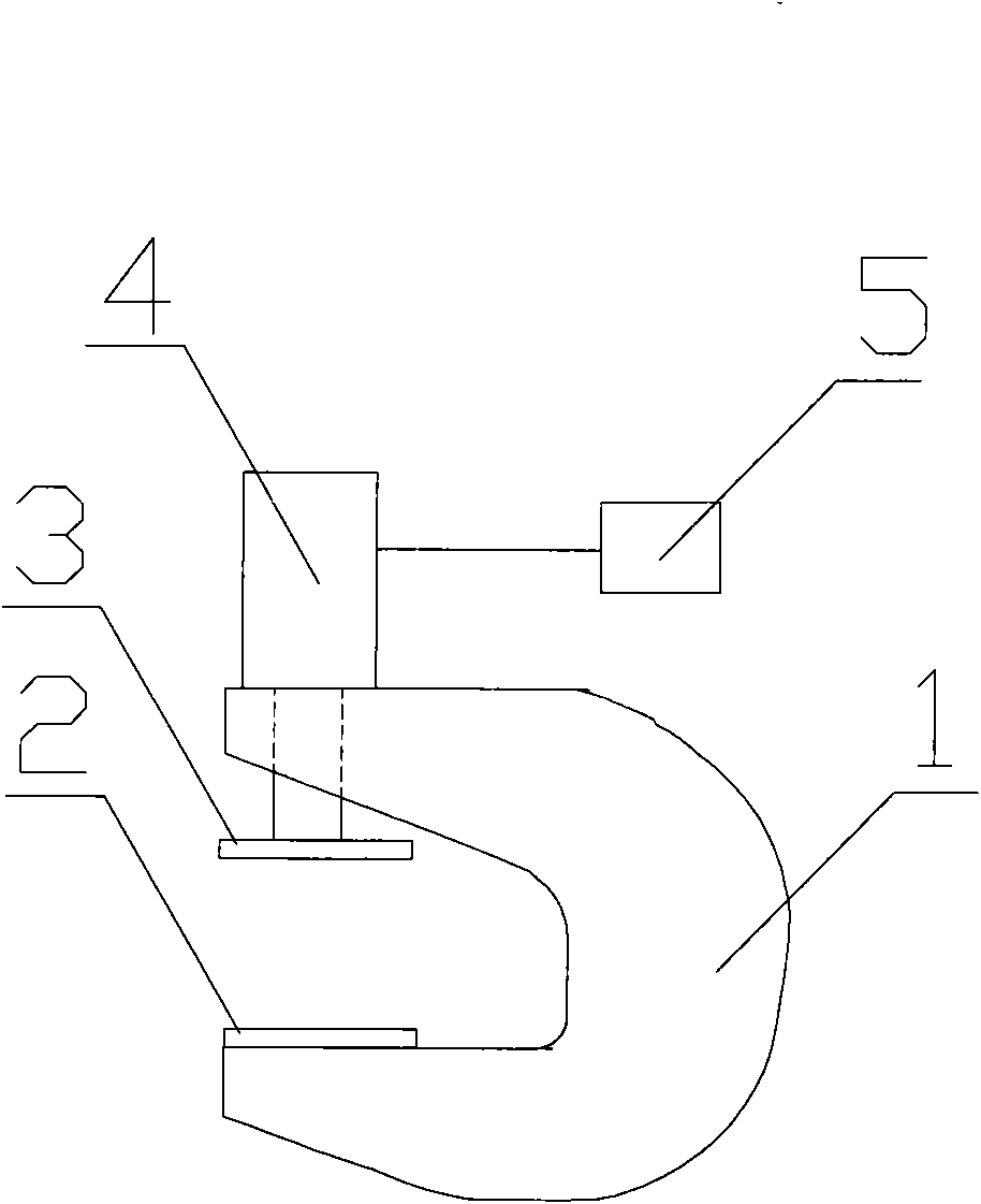
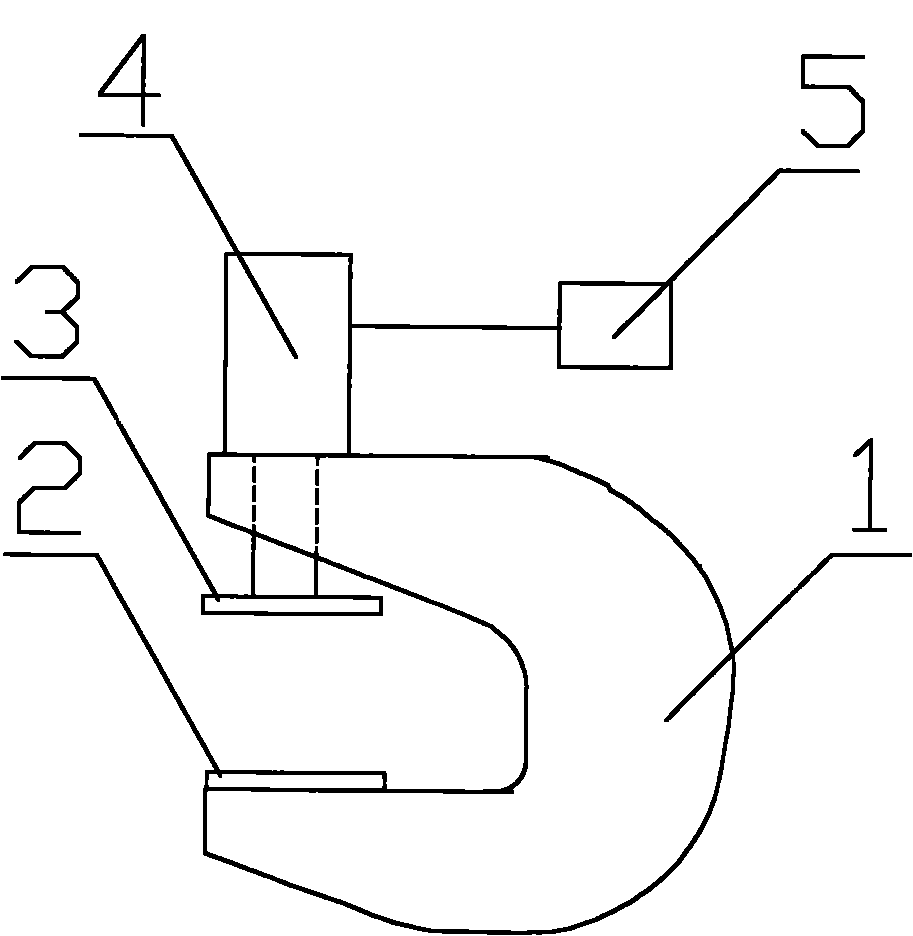
[0012] as attached figure 1 As shown, a tooth pressing device includes a C-shaped pressing tooth main body 1, a horizontal lower metal plate 2 is fixed on the lower part of the pressing tooth main body, and an upper metal plate connected with a hydraulic pump 4 is placed above the lower metal plate 2 3. An oil pressure pump 4 is installed above the pressure gear main body 1, and the oil pressure pump 4 is connected with a switch 5.
Login to View More PUM
 Abstract
The invention discloses a teeth-pressing device, comprising a C-shaped teeth-pressing main body, wherein a horizontal lower part metal plate is fixed at the lower part of the teeth-pressing main body, an upper part metal plate connected with an oil hydraulic pump is arranged above the lower part metal plate, and the oil hydraulic pump connected with a switch is arranged above the teeth-pressing main body. When in use, two wood boards which are required to connect are placed on the lower part metal plate, a toothed metal plate with downward teeth is arranged on the connection part of the wood boards, the switch is started, the upper part metal plate is downwardly pressed by the oil hydraulic pump to nail the teeth in the two wood boards so as to achieve the aim of connecting the wood boards. Since the pressure is provided by the oil hydraulic pump to downward press the metal plate, the connection part is smooth and the connection effect is good.
Description
technical field [0001] The invention relates to a gear pressing device, in particular to a gear pressing device which can move freely. Background technique [0002] At present, planks are generally connected by connectors. For example, the publication number is CN201212233, which is named as an invention patent of a connector for planks. It consists of two positioning pieces and a connecting piece. The two positioning pieces are respectively located on the left and right sides of the connecting piece. The cross section of the plank connector is similar to the shape of "I". The positioning piece is left-right symmetrical with respect to the plane where the connecting piece is located. These connectors have certain advantages for connecting relatively short wooden boards, and are convenient to use. [0003] However, these connection methods are not necessarily applicable when the length and weight of the planks to be connected are relatively large. [0004] At present, when...
Claims
Login to View More Application Information
Patent Timeline
 Patent Type & AuthorityApplications(China)
IPC IPC(8): B27D1/10B27F7/00
Inventor商继红陈昌安
OwnerCHENGDU CANYA WOOD IND