Mold for tyre

A technology of tires and molds, which is applied to household appliances, other household appliances, tires, etc., can solve problems such as the inability to manufacture tires, and achieve the effect of improving productivity

Inactive Publication Date: 2011-04-27
SUMITOMO RUBBER IND LTD
View PDF8 Cites 5 Cited by
  • Summary
  • Abstract
  • Description
  • Claims
  • Application Information

AI Technical Summary

Problems solved by technology

The mold cannot make tires that do not require such grooves
The mold has the problem of only making tires with a certain shape

Method used


Image

  • Mold for tyre
  • Mold for tyre
  • Mold for tyre

Examples


Embodiment 1

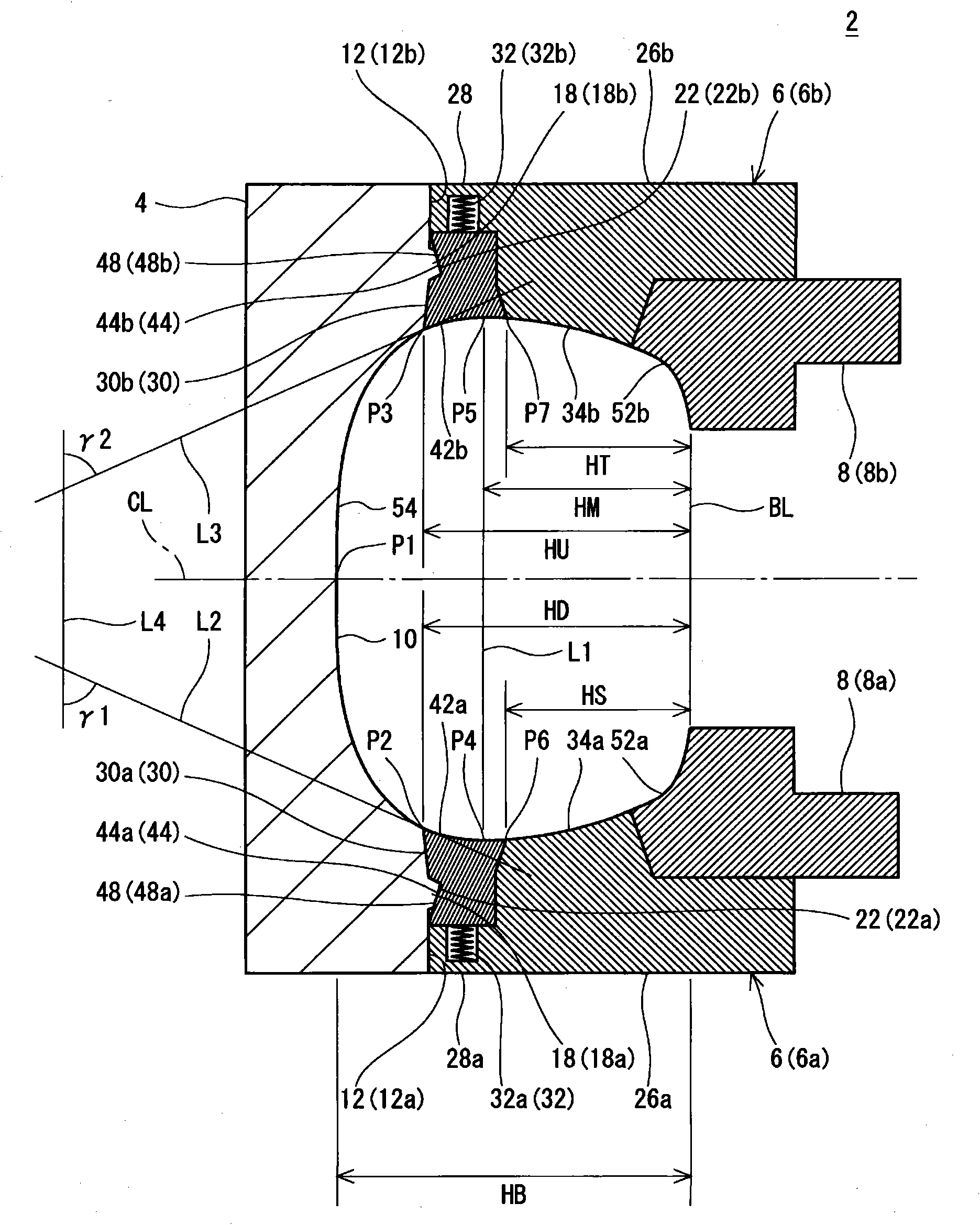
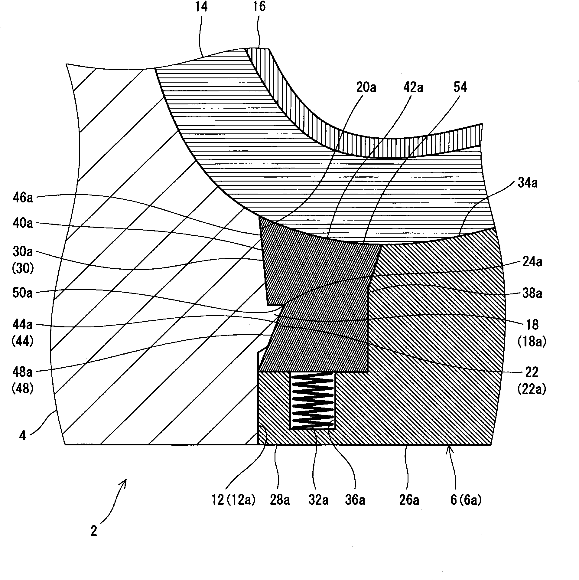
[0065] in possession figure 2 A raw tire was placed in the tire mold of Example 1 having the basic configuration shown and the specifications shown in Table 1 below to manufacture a tire (tire size = 195 / 65R15). In this production, a raw tire is placed in a tire mold in which the split mold is separated from the side plate and the movable ring is moved axially inward. After filling the air bag with gas and shaping the green tire, the combined mold is moved radially inward. Through this movement, the split mold comes into contact with the side plate, and the movable ring moves axially outward while the conical surface of the movable ring slides along the slope of the split mold, and the molding surfaces of the components are combined to form the cavity surface. The mold is thus closed, and the green tire is pressurized and heated in the mold to obtain a tire. The length LD of the molded surface of the lower movable ring was 5 mm. The moving distance (distance SD) of this mo...

Embodiment 2~9

[0067] The length LD, the length LU, the distance SD, and the distance SU were the same as in Example 1 except that they were shown in Table 1 below, and tires were manufactured.


PUM

PropertyMeasurementUnit
lengthaaaaaaaaaa

Abstract

The invention discloses a mold (2) for tyre aiming at obtaining tyre with high quality. The mold herein comprises a plurality of combination molds (4), and side plates (6) which are disposed on inner sides in radial direction of each combination mold, wherein each combination mold is provided with a division surface (12) that is oppositely disposed to the side plate (6). The division surface is provided with an inclined plane (22) which inclines from the axis inner side to the outer side and to the radial outer side. The side plate (6) is provided with a movable ring (30) which abuts the division surface, and an actuator (32) which can apply force to the movable ring (30) to the axis inner side. The movable ring (30) is provided with a conical surface (48) which corresponds to the inclined plane (22). If the combination molds (4) depart from the side plates (6), the movable ring (30) will move to the axis inner side. If the combination molds (4) comes close to the side plates (6) and the inclined plate (22) abuts the conical surface (48), the conical surface (48) will slides along the inclined plate (22) and at the same time the movable ring (30) will move to the axis outer side.

Description

technical field [0001] The invention relates to a tire mold. Background technique [0002] Molds are used in the vulcanization process of tires, and the molds are roughly divided into sheet molds and two-half molds. From the viewpoint of increasing the degree of freedom of the tread pattern, sheet molds have been mainly used in recent years. [0003] The sheet mold has multiple combined molds, a pair of upper and lower side plates and a pair of upper and lower bead rings. The planar shape of each split mold is substantially arc-shaped. A plurality of split molds are connected in a ring shape. The side panels and bead rings are substantially annular. An example of such a die is disclosed in Japanese Patent Application Laid-Open No. 7-164449. [0004] During the vulcanization process, the green tire is placed in an open mold. The air bag is deflated when placed in the raw tire. The air bag is inflated by filling it with gas. The green tire is deformed by this expansion...

Claims


Application Information

Patent Timeline
Patent Type & Authority Applications(China)
IPC IPC(8): B29C33/38B29D30/08B29C35/02B29C33/42B29L30/00
CPCB29D30/0629
Inventor 坪井朝一
Owner SUMITOMO RUBBER IND LTD
Why Eureka
Try Eureka