
Inverter malfunction stop system

An inverter and malfunction technology, which is applied in the field of on-board control systems of railway vehicles, can solve the problems of increasing the cost of the inverter, and achieve the effect of reducing the cost increase and preventing dangerous events.

Inactive Publication Date: 2011-04-27
HITACHI LTD
View PDF5 Cites 0 Cited by
  • Summary
  • Abstract
  • Description
  • Claims
  • Application Information

AI Technical Summary

Problems solved by technology

[0008] In order to prevent such accidents, it is considered necessary to improve the reliability of the logic part of the inverter. Therefore, the increase in the cost of inverter production, such as updating the hardware structure and increasing the software production process, has become a problem.

Method used


Image

  • Inverter malfunction stop system
  • Inverter malfunction stop system
  • Inverter malfunction stop system

Examples


Embodiment 1

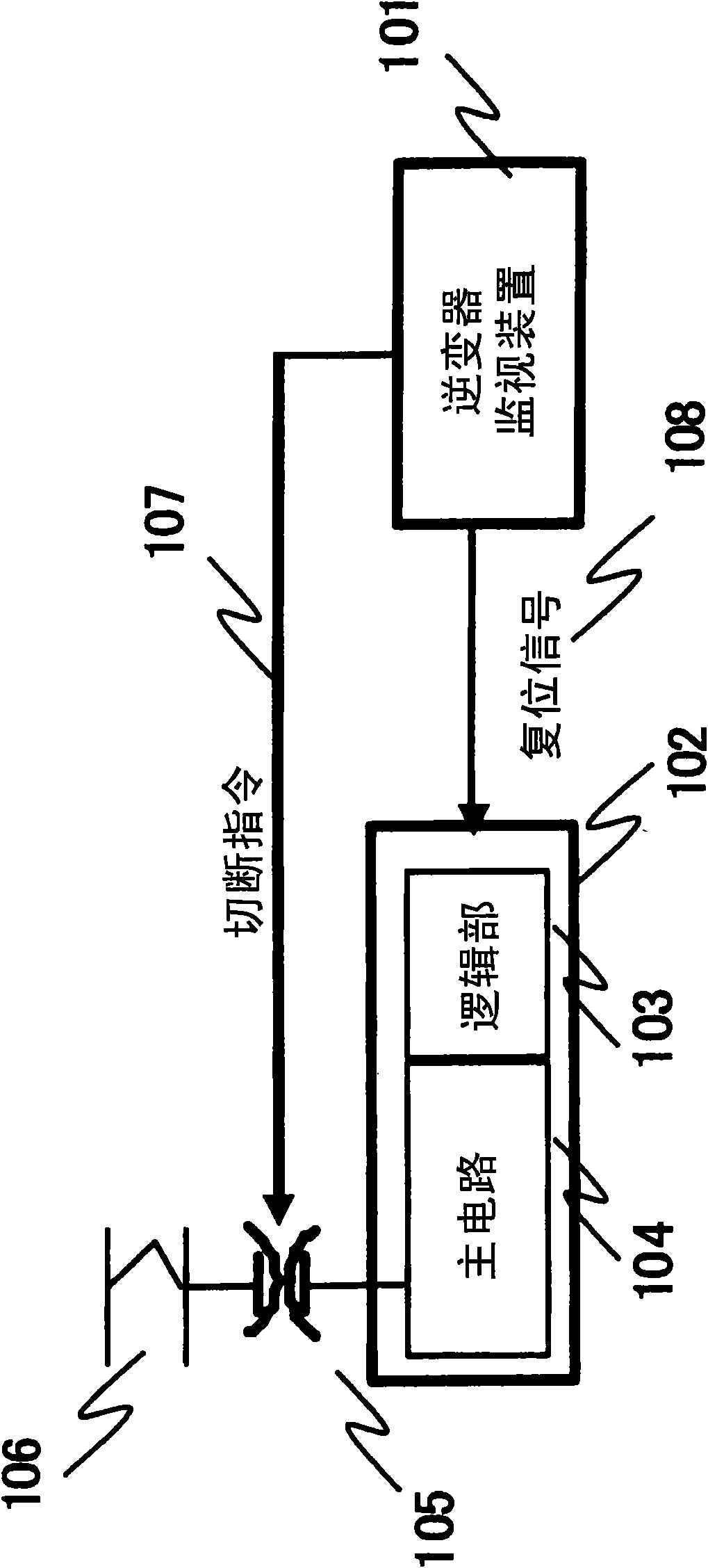
[0022] figure 1 The system configuration of the inverter malfunction stop system in Embodiment 1 of the present invention is shown. In the present invention, the combination of the inverter logic unit 103 and the main circuit 104 is called an inverter 102 .

[0023] The inverter monitoring device 101 monitors whether the inverter 102 operates correctly. The method of how to judge whether the operation is correct or not will be described in detail later. When a malfunction of the inverter 102 is detected, the inverter monitoring device 101 forcibly stops the operation of the inverter 102 .

[0024] As a method of stopping the inverter 102, it is conceivable to output a cutoff command 107 to cut off the current supplied from the pantograph 106 to the main circuit 104; and to output a reset signal 108 to the inverter logic unit 103 to reset the inverter. Inverter logic part 103, or continue to output the reset signal 108 to stop the operation of the inverter logic part.

[00...

Embodiment 2

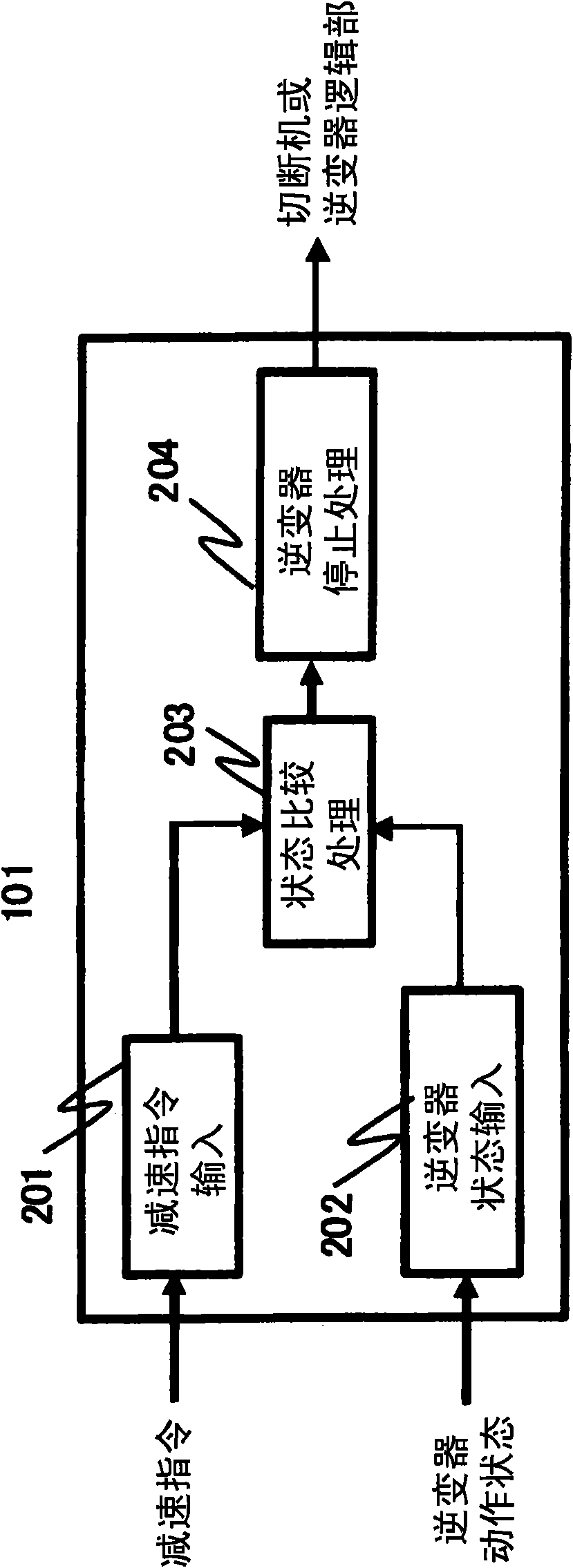
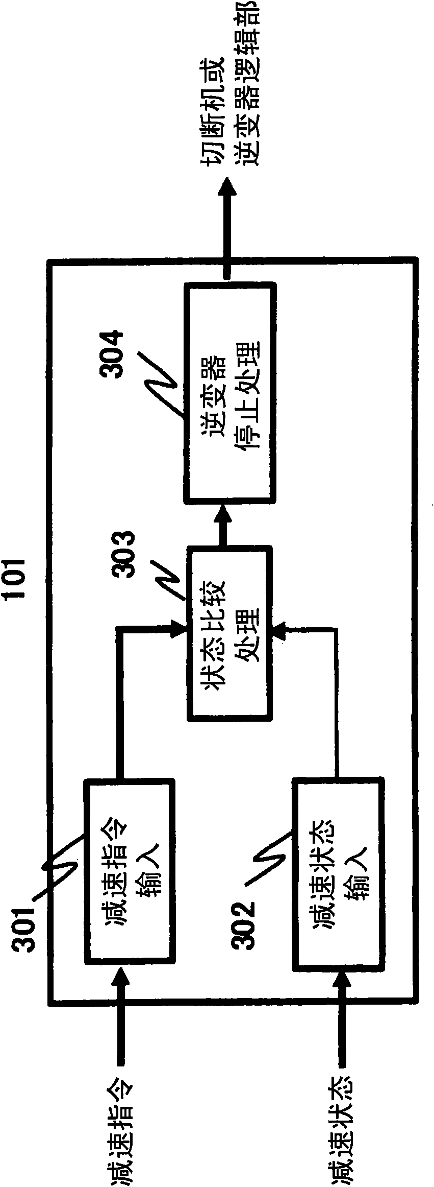
[0043] In Embodiment 1, the inverter 102 is stopped when the inverter 102 does not decelerate and the deceleration of the train is insufficient for the deceleration command, but in the same device configuration, the inverter 102 malfunctions and the acceleration command is stopped This malfunction can also be detected without acceleration.

[0044] The consideration method is the same as that of embodiment 1, in Figure 4 and Figure 5 , as long as the figure 2 and image 3 The deceleration command in is set to the acceleration command. That is, an acceleration command is input to the inverter monitoring device 101 . taking Figure 4 In the case of this configuration, if the acceleration command and the operating state of the inverter 102 do not match, it is determined that the inverter 102 has malfunctioned.

[0045] or, in taking Figure 5 In the case of the configuration, the acceleration of the train as a railway vehicle is monitored to monitor whether the accelera...


PUM


Abstract

The invention provides an inverter malfunction stop system. In a past railway accident, a malfunctioning logic unit of an inverter could not receive acceleration commands, according to which the logic unit maintained the previously received acceleration command and the inverter maintained acceleration while the train is attempting to decelerate, which lead to an accident since it was impossible to obtain the desired deceleration. In order to overcome this problem, the reliability of the inverter logic unit must be improved. The present invention provides an inverter monitoring apparatus independently from an inverter, and when malfunction of the inverter is detected, a high-speed circuit breaker or the like is activated to disconnect a main circuit and the operation of the inverter is stopped forcibly, or a logic unit of the inverter is reset, for example, so as to prevent dangers caused by the malfunction of the inverter.

Description

technical field [0001] The present invention relates to an on-board control system in a railway vehicle having an inverter, and more particularly to an on-board control system for a railway vehicle that stops the operation of the inverter after detecting a malfunction of the inverter. Background technique [0002] Generally, when the inverter fails, the motor is in a failure mode in which it cannot operate normally, so that dangerous events such as derailment and collision will not be caused by the failure of the inverter. The reason for this is that the motor does not operate unless the correct control is performed, so when the inverter fails and the output is abnormal, the motor does not operate. [0003] On the other hand, various safety measures are taken against the failure of the main circuit of the inverter. For example, when a short-circuit fault occurs in the main circuit, the worst case is a short-circuit from the overhead wire to the rail, and a large current may...

Claims


Application Information

Patent Timeline
Patent Type & Authority Applications(China)
IPC IPC(8): B61L3/00
CPCH02M1/32
Inventor 前川景示小川岳永次由英
Owner HITACHI LTD
Learn More