Rear suspension system of automobile longitudinal power assembly

A technology of powertrain and rear suspension, applied in the direction of control device, vehicle components, substructure, etc., can solve the problems of low position of gearbox, adjustment of elastic components, and small space for gearbox cushion, and achieve volume and compression. added effect

Inactive Publication Date: 2011-04-27
郑州日产汽车有限公司
View PDF5 Cites 5 Cited by
  • Summary
  • Abstract
  • Description
  • Claims
  • Application Information

AI Technical Summary

Problems solved by technology

However, the configuration of the automobile powertrain requires the position of the gearbox to be as low as possible, resulting in too little space for the cushion of the gearbox, and the cushion cannot provide enough volume and movement space to achieve the proper shock absorption and shock isolation effects. At the same time, due to the vertical arrangement of the elastic elements, the center of action of the elastic elements cannot be adjusted according to the moment of inertia of the powertrain, so as to achieve the optimization of the suspension system arrangement

Method used


Image

  • Rear suspension system of automobile longitudinal power assembly
  • Rear suspension system of automobile longitudinal power assembly
  • Rear suspension system of automobile longitudinal power assembly

Examples


Embodiment 1

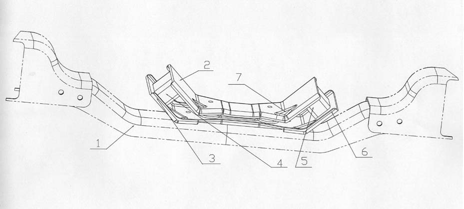
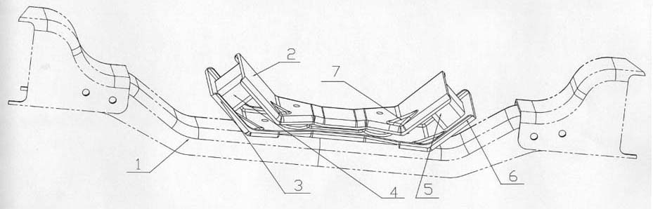
[0012] Such as figure 1 As shown, the rear suspension system of the automobile longitudinal powertrain according to the present invention includes an upper bracket 2, a lower bracket 3 arranged on the gearbox lower beam 1, and a group of elastic elements 4 arranged between them , 5, the upper bracket 2 and the lower bracket 3 extend upwardly from both sides of the gearbox, and the elastic elements 4, 5 are arranged between the upper and lower brackets 2, 3 on both sides of the gearbox; The sides of the lower brackets 2, 3 have flanges 6, and the middle parts of the upper and lower brackets 2, 3 are provided with reinforcing ribs 7.

[0013] The middle position of the upper surface of the upper bracket 2 is connected to the gearbox body through bolts, and the lower surfaces on both sides are connected to the elastic elements 4 and 5 through bolts or bonding; the upper surfaces on both sides of the lower bracket 3 are connected to the The elastic elements 4 and 5 are connected,...

Embodiment 2

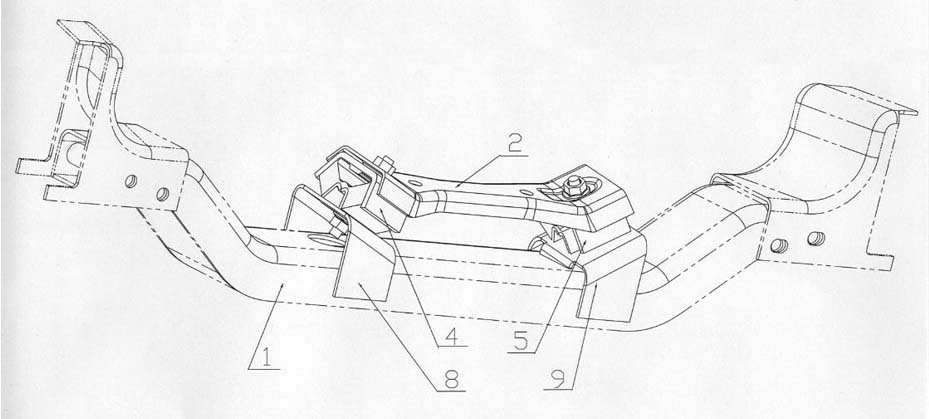
[0015] The rear suspension system of the automobile longitudinal powertrain according to the present invention comprises an upper bracket 2, a lower bracket 3 arranged on the lower beam 1 of the gearbox, and a group of elastic elements 4, 5 arranged between them, In order to make its structure compact, the lower bracket 3 can be simplified as a pair of support slant plates 8, 9 directly welded on the gearbox lower beam 1, as figure 2 As shown, the elastic elements 4, 5 are bolted (or bonded) on the support swash plates 8, 9, and then the lower surfaces on both sides of the upper bracket 2 are connected to the elastic elements 4, 5 by bolts or bonding; The direct welding between the lower beam 1 of the gearbox and the lower bracket (that is, the support slant plates 8, 9) ensures the rigidity of the lower bracket, and at the same time, due to the simplicity of the parts and the flexibility of the design, it is possible to reduce the cost of the suspension system .


PUM


Abstract

The invention discloses a rear suspension system of an automobile longitudinal power assembly, which comprises an upper bracket, a lower bracket and an elastic element, wherein the upper bracket and the lower bracket are arranged on a lower beam of the transmission case and obliquely extend upwards from both sides of the transmission case; and the elastic element is arranged between the upper bracket and the lower bracket arranged on both sides of the transmission case. On the premise of not changing the prior automobile power assembly and the vertical space relationship of the transmission case beam, the cushion room is increased and the action center of the elastic element is changed. The upper and lower brackets obliquely extend upwards from both sides of the transmission case, and the elastic element is arranged between the upper and lower brackets on both sides of the transmission case, so that the upward and downward arrangement of the elastic element is not restricted by the transmission case and the volume and amount of compression of the elastic element can be obviously increased as compared with those in the original design. Meanwhile, since the space permits, the elastic element and the horizontal surface can form an included angle, thereby optimizing the arrangement of the suspension system.

Description

technical field [0001] The invention relates to a rear suspension system of an automobile vertical power assembly. Background technique [0002] The lower beam of the automobile gearbox cushion is usually the lowest point of the vehicle frame. In order to ensure the passability of the whole vehicle, there is a certain height limit between the lower beam and the ground. However, the configuration of the automobile powertrain requires the position of the gearbox to be as low as possible, resulting in too little space for the cushion of the gearbox, and the cushion cannot provide enough volume and movement space to achieve the proper shock absorption and shock isolation effects. At the same time, due to the vertical arrangement of the elastic elements, the center of action of the elastic elements cannot be adjusted according to the moment of inertia of the powertrain to optimize the arrangement of the suspension system. Contents of the invention [0003] The object of the pr...

Claims


Application Information

Patent Timeline
Patent Type & Authority Applications(China)
IPC IPC(8): B62D21/09B60K17/06
Inventor 王桂群宋珍龚晓龙高嘉高立杰
Owner 郑州日产汽车有限公司
Why Eureka
Try Eureka