Weft insertion device of air-jet loom

A technology of air jet loom and weft insertion device, which is applied in looms, textiles, textiles and paper making, etc., can solve the problems of difficulty in ensuring the stability of weft insertion and the decrease of flying speed.

Active Publication Date: 2011-04-27
TOYOTA IND CORP
View PDF6 Cites 11 Cited by
  • Summary
  • Abstract
  • Description
  • Claims
  • Application Information

AI Technical Summary

Problems solved by technology

In the weft insertion device according to the above disclosure, if the air tank pressure for the distal auxiliary nozzle is set lower than the air tank pressure for the we

Method used


Image

  • Weft insertion device of air-jet loom
  • Weft insertion device of air-jet loom
  • Weft insertion device of air-jet loom

Examples


Embodiment Construction

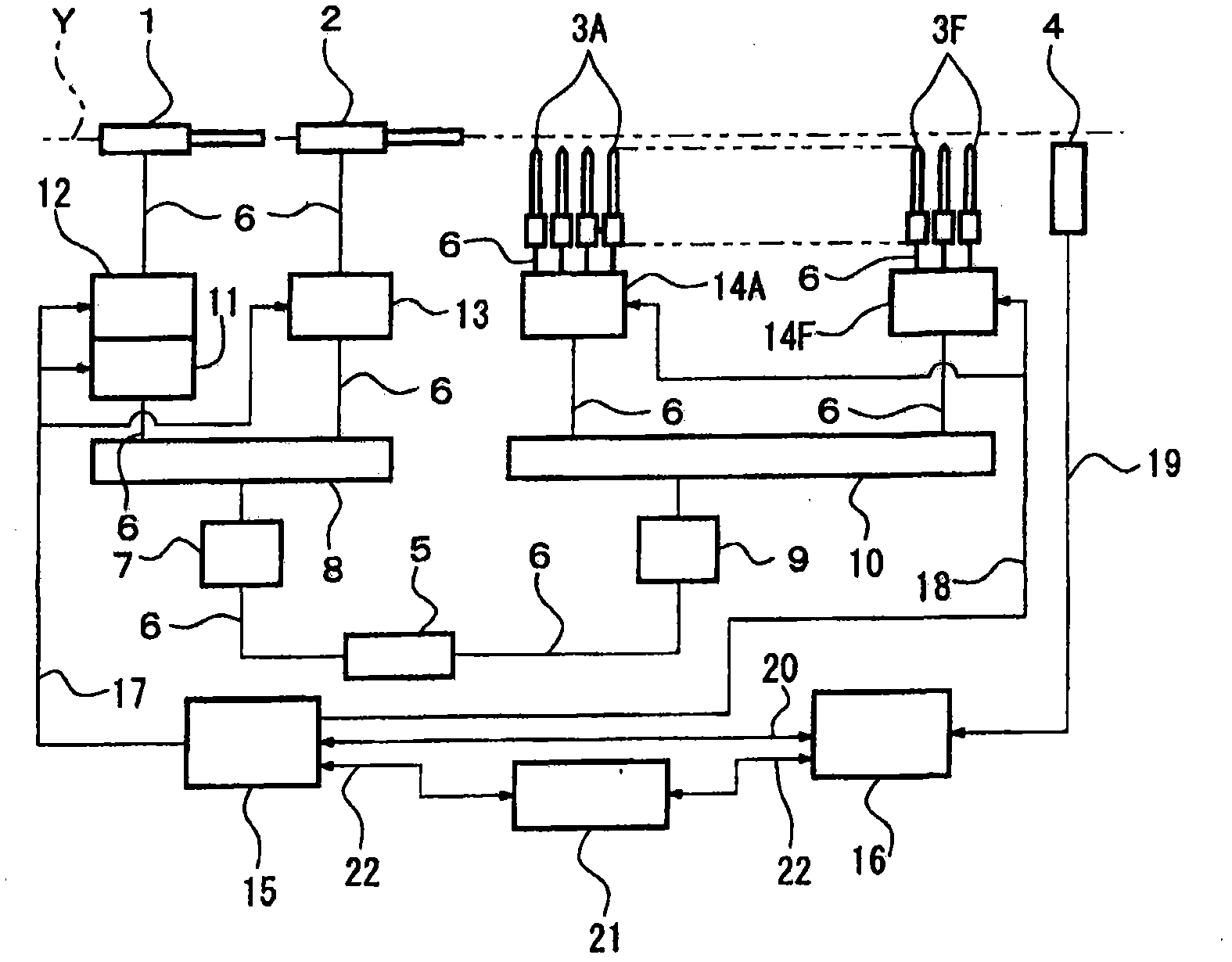
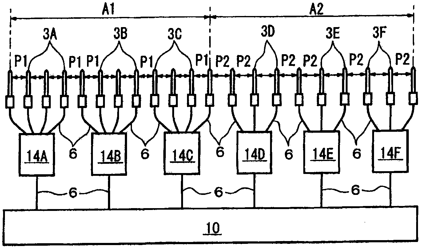
[0014] The following will refer to Figure 1 to Figure 3 A first embodiment will be described. refer to figure 1 The weft yarn Y passed through the weft yarn feeder (not shown) and the weft yarn length measuring device (not shown) is pulled by the tandem nozzle 1, and then inserted by the main nozzle 2 into the weft yarn passage in the warp yarn (not shown) shed. Then, the weft yarn Y inserted by the main nozzle 2 is assisted in flight by air jets emitted from a plurality of auxiliary nozzles 3A to 3F (only 3A and 3F are shown in the figure) arranged at intervals along the weft yarn path. The insertion of the weft yarn Y ends when the weft yarn reaches a predetermined position beyond the end of the fabric positioned relative to the other end of the fabric adjacent to the main nozzle 2 . The weft yarn detector 4 detects the leading end of the continuously inserted weft yarn Y.

[0015] The air supply part 5 is connected to the main tank 8 and the auxiliary tank 10 through th...


PUM


Abstract

The present invention relates to a weft insertion device of an air-jet loom, which comprises the following components: a weft yarn channel which is provided in a shed of twist yarn, a main nozzle which inserts the weft yarn into the weft yarn channel through air jet, and a plurality of auxiliary nozzles which are separately placed along the weft yarn channel and carry the inserted weft yarn to the downstream part through air jet. The plurality of auxiliary nozzles are divided into a plurality of areas along the weft yarn channel. The auxiliary nozzles in the downstream area along the weft yarn channel are separately placed with a certain distance from one another, wherein the distance is larger than the that of the auxiliary nozzles in the upstream area along the weft yarn channel.

Description

technical field [0001] The present invention relates to a weft insertion device of an air-jet loom, wherein the weft thread inserted into an open shed by means of a main nozzle is conveyed through the shed by an auxiliary nozzle. Background technique [0002] Japanese Patent Application Publication H02-47335 discloses a weft insertion method that stabilizes the weft insertion process, and also by means of changing the air jet pressure, the flight speed of the weft yarn in the reed, the weft insertion side and the relatively far side of the air-jet loom. The injection time of the auxiliary nozzles in the interval can be used to improve the starting performance of the weft insertion process, thereby obtaining high-speed operation of the air-jet loom. [0003] More specifically, the plurality of auxiliary nozzle groups are divided into two areas, one area is located on the weft insertion side, and the other area is located on the far side. The air injection pressure of the aux...

Claims


Application Information

Patent Timeline
IPC IPC(8): D03D47/30
CPCD03D47/302D03D47/3033D03D47/3053
Inventor 高木信次荒井隆二
Owner TOYOTA IND CORP
Why Eureka
Try Eureka