
Method for realizing pressure tapping by using gas drainer and gas drainer for realizing pressure tapping

A drainer and gas technology, applied in gas/liquid distribution and storage, pipeline systems, mechanical equipment, etc., can solve the problem of single function of the gas drainer, and achieve the effect of expanding the scope of use, simple method, and efficient use of equipment

Active Publication Date: 2013-03-27
秦皇岛莱特流体设备制造有限公司
View PDF4 Cites 1 Cited by
  • Summary
  • Abstract
  • Description
  • Claims
  • Application Information

AI Technical Summary

Problems solved by technology

[0003] The current gas drainer has a relatively single function, which is only used to block the gas, but in today's pursuit of high efficiency, it is urgent to use material resources and energy efficiently

Method used


Image

  • Method for realizing pressure tapping by using gas drainer and gas drainer for realizing pressure tapping
  • Method for realizing pressure tapping by using gas drainer and gas drainer for realizing pressure tapping
  • Method for realizing pressure tapping by using gas drainer and gas drainer for realizing pressure tapping

Examples


Embodiment Construction

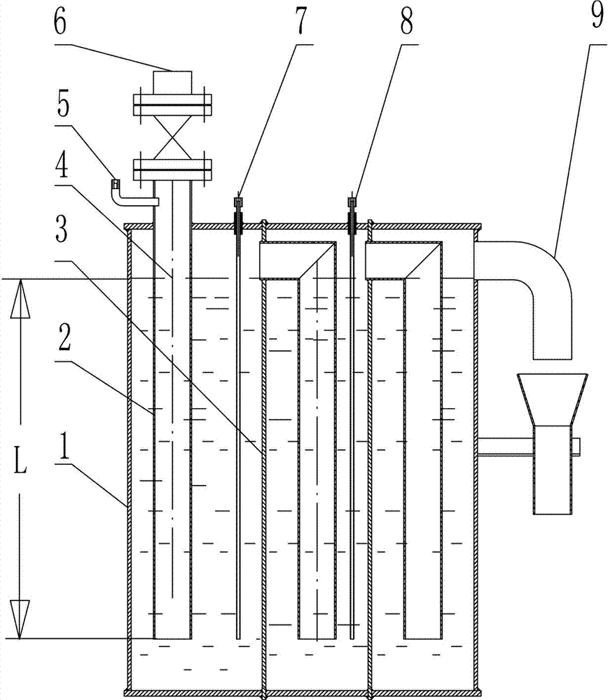
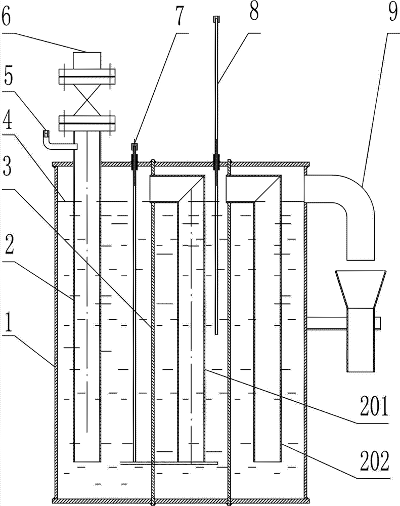
[0021] The gas drainer realizing the pressure taking method of the present invention can be composed of N horizontal connectors connected in series, the water seal chambers of each connector contain water for blocking gas, and a water seal pipe is erected in each water seal chamber , the lower end of each water-sealed tube is suspended, and the upper port of each water-sealed tube in the water-sealed chamber of the connector from the second stage to the last stage is connected with the water-sealed chamber of the previous stage; the upper port of the first-stage connector serves as a receiving port The inlet of the gas pressure, and the outlet connected to the atmosphere is opened on the last stage of the connector.

[0022] The gas drain can also be as figure 1 , figure 2 The form of the embodiment shown is integrated, that is, it includes an airtight drain housing 1, an inlet 6 is arranged on one side of the airtight drain housing 1 for communicating with the gas, and an o...


PUM


Abstract

The invention discloses a gas drainer and a method for realizing pressure tapping by using the gas drainer. The gas drainer is provided with N horizontal communicating vessels which are connected in series with one another, wherein water is filled in a water sealing chamber of each communicating vessel and a water sealing pipe is vertically arranged in the water sealing chamber; the lower end of each water sealing pipe is open; the upper ports of the second stage of water sealing pipe to the final stage of water sealing pipe are communicated with previous stages of water sealing chambers; the upper port of the first stage of communicating vessel is an inlet for receiving gas pressure; and the final stage of communicating vessel is provided with an outlet which is communicated with atmosphere. The method for realizing pressure tapping by using the gas drainer comprises the following steps that: the top of a water sealing chamber accommodating chamber between every two adjacent water sealing pipes is provided with a pressure tapping port; each port is provided with a sealed pressure tapping adjustment pipe which can adjust the length of the part inserted into plugging water within a vertical length L range; the pressure tapping port is directly formed above the first stage of water sealing pipe; or as required, extension length of the pressure tapping adjustment pipe at a corresponding port is adjusted to realize pressure tapping at the pressure tapping port, or the pressure tapping port is directly formed above the water sealing pipe of the first stage of communicating vessel to tap pressure Vmax. The method can expand the application of the gas drainer and can be easily mastered by operation personnel.

Description

technical field [0001] The invention belongs to the related technology of special protection equipment for gas pipeline system drains, in particular to a method for taking pressure by using a gas drain and a gas drain capable of realizing pressure. Background technique [0002] The gas drainer is a special equipment for blocking the gas. It uses the built-in water column with a certain height to block the gas. It can also use the connector structure of the gas drainer to smoothly discharge the condensed water in the gas. [0003] The function of the current gas drainer is relatively simple, and it is only used to block the gas. Today, in the pursuit of high efficiency, it is urgent to use material resources and energy efficiently. Contents of the invention [0004] The object of the present invention is to provide a method for taking pressure by using a gas drainer, which can broaden the usage of the gas drainer and is easy to be grasped by operators. [0005] To achieve ...

Claims


Application Information

Patent Timeline
Patent Type & Authority Patents(China)
IPC IPC(8): F17D3/14
Inventor 李建勇林自力
Owner 秦皇岛莱特流体设备制造有限公司
Learn More