Backlight module

A backlight module, light source technology, used in optics, light guides, light sources, etc.

Inactive Publication Date: 2011-04-27
AU OPTRONICS CORP
View PDF5 Cites 8 Cited by
  • Summary
  • Abstract
  • Description
  • Claims
  • Application Information

AI Technical Summary

Problems solved by technology

[0006] The technical problem to be solved by the present invention is to provide a backlight module that can solve the problems caused by the deformation of the light guide plate due to different environments.

Method used


Image

  • Backlight module
  • Backlight module
  • Backlight module

Examples


Embodiment Construction

[0035] Below in conjunction with accompanying drawing, structural principle and working principle of the present invention are specifically described:

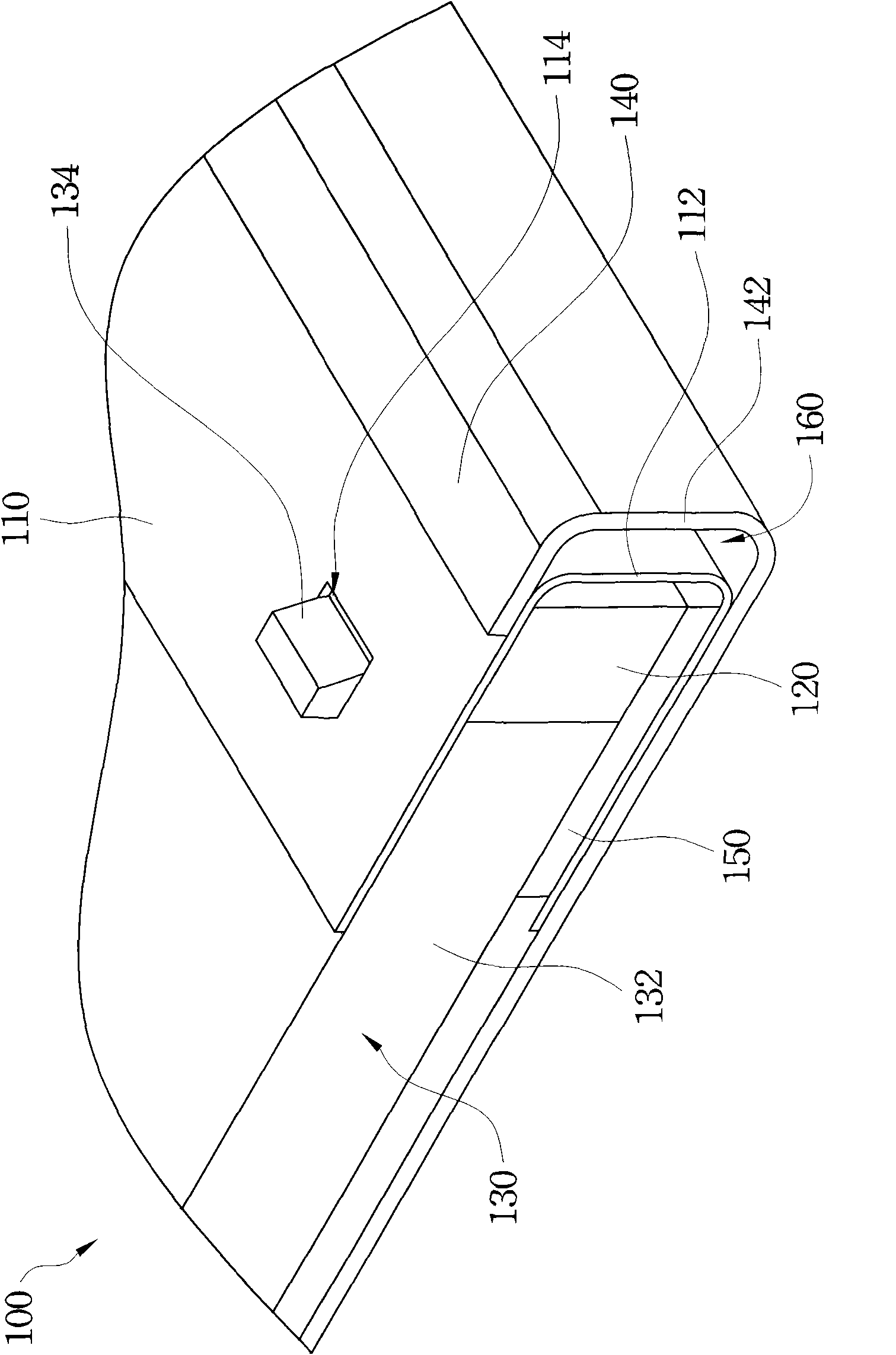
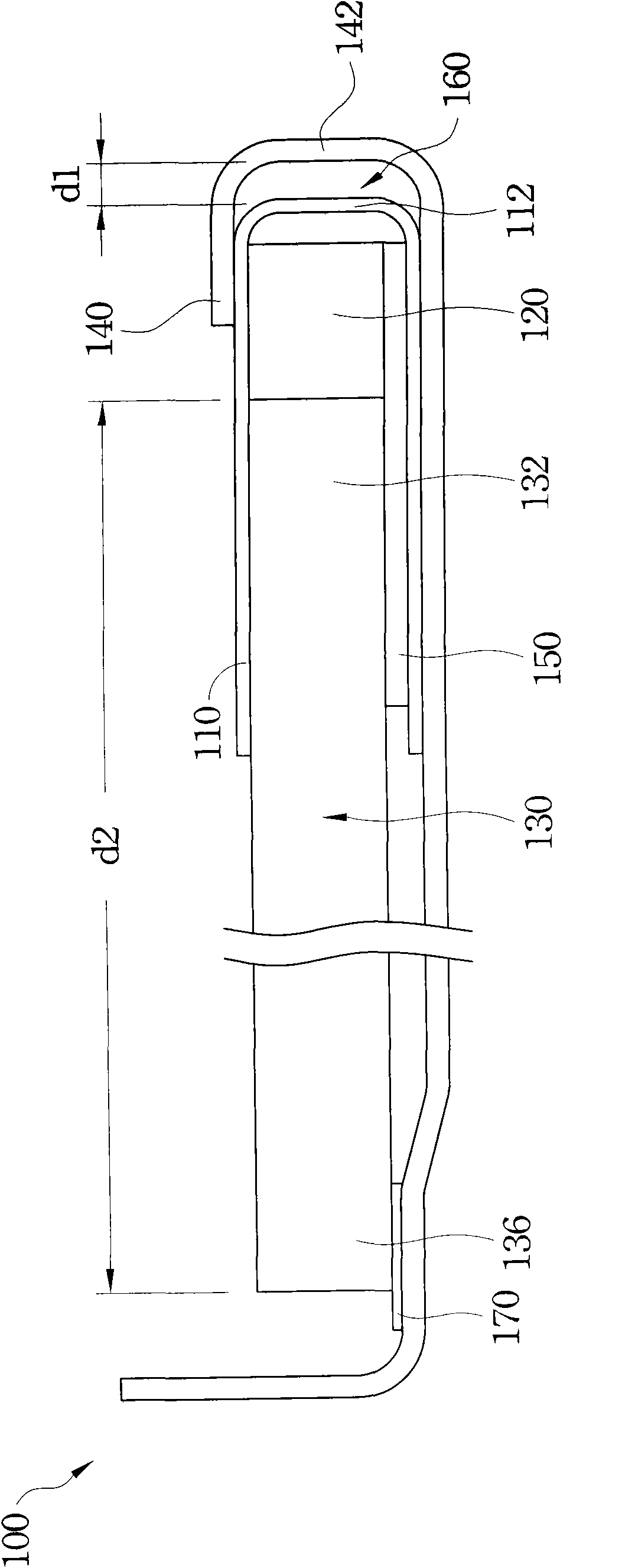
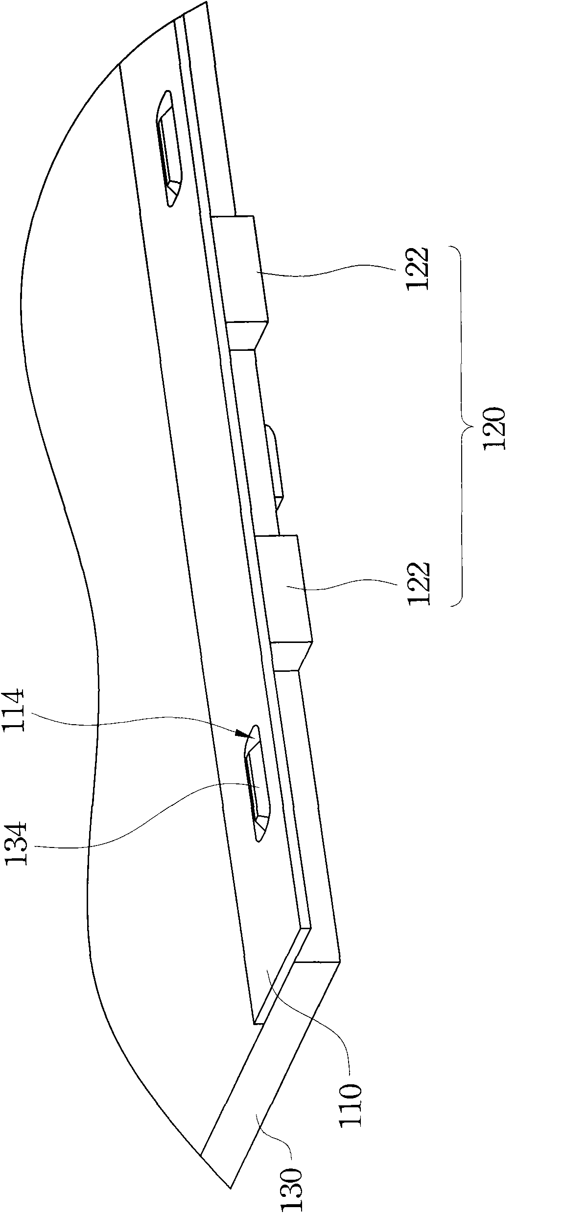
[0036] refer to figure 1 , which is a partial schematic diagram of the first embodiment of the backlight module of the present invention. The backlight module 100 includes a bracket 110 , a light source 120 , a light guide plate 130 , a frame 140 and a circuit board 150 . The light source 120 is arranged on the bracket 110, more specifically, the bracket 110 is type bracket, and in its The other side of the type relative to the opening is the bracket side wall 112, and the aforementioned light source 120 is arranged on the bracket 110 to form type of space. One end 132 of the light guide plate 130 is fixed on the bracket 110 , in other words, one end 132 of the light guide plate 130 extends from the bracket 110 The light source 120 protrudes into the type opening and abuts against the light source 120 . The circuit b...


PUM


Abstract

A backlight module comprises a bracket, a light source, a light guiding plate and an outer frame. The light source is equipped on the bracket. One end of the light guiding plate is fixed on the bracket. The bracket is combined with the outer frame, wherein a clearance is provided between the side wall of the bracket and the side wall of the outer frame for acting as a buffer space for deformation of the light guiding plate. When the light guiding plate of the invention expands because of different environment, the surface of the light guiding plate can be kept flat. Additionally, the light guiding plate and the light source are all fixed on the bracket. Therefore, when the light guiding plate shrinks because of the different environments, a phenomenon of light leakage is prevented.

Description

technical field [0001] The invention relates to a display, in particular to a backlight module of the display. Background technique [0002] Liquid Crystal Display (LCD) has the advantages of high image quality, small size, light weight, low voltage drive, low power consumption and wide application range, so it has been widely used in portable TVs, mobile phones, video recorders, etc. In consumer electronics or computer products such as video projectors, notebook computers, and desktop displays, it has become the mainstream of displays. [0003] A liquid crystal display mainly includes components such as a liquid crystal panel, a backlight module, and a frame. The backlight module is used to provide a light source, and mainly includes components such as a light strip, a light guide plate, and a plastic frame. The liquid crystal panel can be fixed on the plastic frame of the backlight module through an adhesive member such as double-sided tape to position the liquid crystal...

Claims


Application Information

Patent Timeline
Patent Type & Authority Applications(China)
IPC IPC(8): F21S8/00F21V8/00F21V17/10F21V19/00G02F1/13357F21Y101/02
CPCG02B6/009G02F1/133308G02B6/0088G02B6/0011G02F1/133615
Inventor 黄达人
Owner AU OPTRONICS CORP
Why Eureka
Try Eureka