Optical display system

An optical display and display system technology, applied in optics, optical components, instruments, etc., can solve the problems of information leakage, small viewing angle, and high price, and achieve the effects of avoiding information leakage, small image distortion, and wide moving range

Pending Publication Date: 2018-09-25
NINGBO HONGYI OPTO ELECTRONICS CO LTD
View PDF0 Cites 2 Cited by
  • Summary
  • Abstract
  • Description
  • Claims
  • Application Information

AI Technical Summary

Problems solved by technology

The holographic grating solution is light and thin, with high transmittance, but the process is very complicated, expensive, and the viewing angle is limited; the reflective waveguide requires a responsible coating process and assembly process, which is difficult for mass production and difficult to guarantee imaging consistency; ordinary reflective prisms, the process is simple, but The angle of view is very small; the angle of view of the free-form prism is large, but the process is complicated, mass production is difficult, and the consistency is difficult to guarantee; in addition, some penetrating optical display solutions have the problem that the displayed image is visible to the outside world, causing the information browsed by the user to be perceived by the outside world , the confidentiality is poor, and there will be information leakage
Moreover, the existing optical display system also has problems such as large volume and heavy weight.

Method used


Image

  • Optical display system
  • Optical display system
  • Optical display system

Examples


Embodiment approach 1

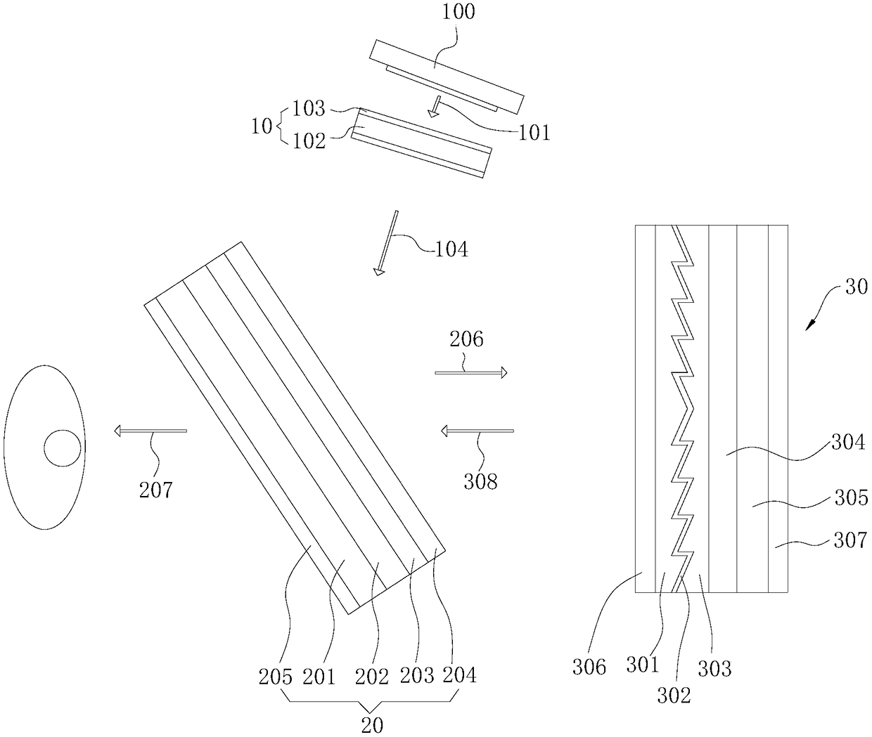
[0032] refer to figure 1 As shown, Embodiment 1 of the present invention provides an optical display system, the optical display system is mainly applied to head-mounted products, such as AR glasses, and the optical display system includes a display system 100, a first optical lens 10, a second optical lens lens 20 and a third optical lens 30 .

[0033] The display system 100 mainly plays the role of emitting light, and the light emitted by the display system 100 is defined as incident light 101 . In this embodiment, the display system 100 is an OLED display system or an LED display system, and the light emitted by the display system 100 is non-polarized light. Of course, the display system 100 can also adopt other display systems 100 that meet the requirements.

[0034] The first optical lens 10 is arranged on the optical path of the incident light 101, and the function of the first optical lens 10 is to reduce field curvature, distortion and dispersion. The quantity of th...

Embodiment approach 2

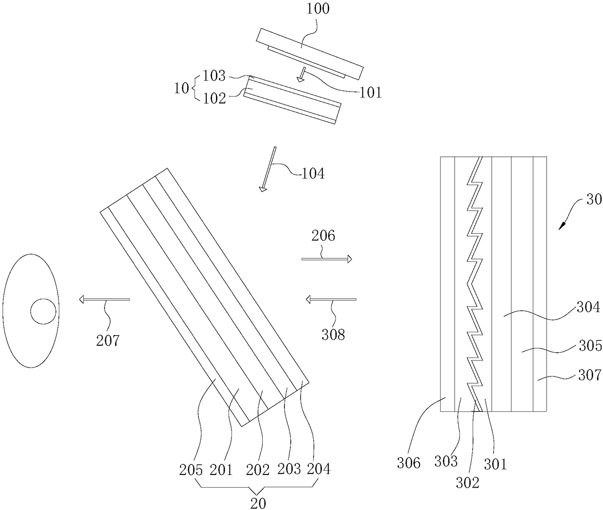
[0051] refer to figure 2 As shown, Embodiment 2 of the present invention provides an optical display system, the optical display system is mainly applied to head-mounted products, such as AR glasses, and the optical display system includes a display system 100, a first optical lens 10, a second optical lens lens 20 and a third optical lens 30 .

[0052] It should be noted that the display system 100, the first optical lens 10 and the second optical lens 20 in this embodiment adopt the display system 100, the first optical lens 10 and the second optical lens 20 in Embodiment 1, and its structure, For the working principle and the generated technical effects, reference may be made to the corresponding content in Embodiment 1, and details are not repeated here.

[0053] The difference between this embodiment and the first embodiment lies in the structure of the third optical lens 30 . In this embodiment, the structure of the third optical lens 30 includes a compensation lens l...

Embodiment approach 3

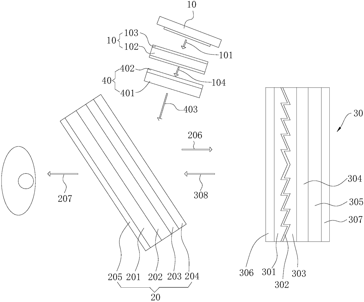
[0060] refer to image 3 As shown, Embodiment 3 of the present invention provides an optical display system. The optical display system is based on the optical display system in Embodiment 1 or on the basis of the optical display system in Embodiment 2. A fourth optical lens is added 40.

[0061] The optical display system of the present embodiment is described by adding the fourth optical lens 40 on the basis of the optical display system of the first embodiment.

[0062] The display system 100 in this embodiment adopts an LCOS display system, and may also adopt an LCD display system. The light emitted by the LCOS display system 100 and the LCD display system 100 is linearly polarized light.

[0063] The fourth optical lens 40 is disposed between the first optical lens 10 and the second optical lens 20 , and is located on the optical path of the first transmitted light 104 .

[0064] The fourth optical lens 40 includes a second optical plate layer 401 and a third quarter-w...


PUM


Abstract

The invention provides an optical display system, belonging to the technical fields of optical imaging and display. The optical display system comprises a display system, a first optics lens, a secondoptics lens and a third optics lens; the light emitted by the display system is incident light, the first optical lens is arranged on the optical path of the incident light, and the light transmittedfrom the first optical lens is first transmitted light; the second optical lens is arranged on the optical path of the first transmitted light, and first reflected light is generated after the firsttransmitted light is treated by the second optical lens; the third optical lens is arranged on the optical path of the first reflected light, the first reflected light is partially reflected after being treated by the third optical lens so as to form second reflected light, and the rest part is absorbed by the third optical lens; the second reflected light is incident into the second optical lens,and the second reflected light is transmitted out after being treated by the second optical lens so as to form second transmitted light. The optical display system has the advantages of being simplein structure, lighter in weight, good in imaging quality and free from light leakage phenomenon, and avoids leakage of information.

Description

technical field [0001] The invention belongs to the technical field of optical imaging, and in particular relates to an optical display system. Background technique [0002] One of the core technologies in the field of Augmented Reality (AR, Augmented Reality) is a penetrating optical display system, which can superimpose computer-generated images on the user's real vision, and seamlessly blend virtual images and real images. The combination of the digital world and the real world will bring users a new experience. At present, AR technology has been widely used in games, retail, education, industry, medical and other fields. [0003] At present, there are holographic gratings, reflective waveguides, ordinary reflective prisms and free-form surface prisms for transmissive optical displays. The holographic grating solution is light and thin, with high transmittance, but the process is very complicated, expensive, and the viewing angle is limited; the reflective waveguide req...

Claims


Application Information

Patent Timeline
IPC IPC(8): G02B27/01G02B27/28
CPCG02B27/0101G02B27/0172G02B27/28G02B2027/0114
Inventor 王锐
Owner NINGBO HONGYI OPTO ELECTRONICS CO LTD
Why Eureka
Try Eureka