Leakage detecting method of vacuum brake device

A vacuum brake and brake hose technology, applied in the direction of liquid tightness measurement using liquid/vacuum degree, and detecting the appearance of fluid at the leakage point, etc., can solve the problem of vacuum brake device damage, low efficiency, and poor effect and other issues, to achieve the effect of improving production efficiency, obvious effect, and low difficulty

Active Publication Date: 2013-01-23
XI AN RAILWAY TRANSPORTATION EQUIP
View PDF0 Cites 0 Cited by
  • Summary
  • Abstract
  • Description
  • Claims
  • Application Information

AI Technical Summary

Problems solved by technology

[0009] The purpose of the present invention is to provide a leak-finding method for a vacuum brake device, which solves the technical problems of low efficiency, poor effect and damage to the vacuum brake device in the background technology

Method used


Image

  • Leakage detecting method of vacuum brake device

Examples


Embodiment Construction

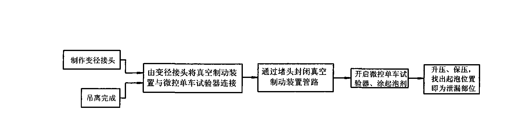
[0029] The leak detection method of the present invention is based on the idea of ​​making a reducing joint and a plug, one end of the reducing diameter is connected to the end of the vacuum device, and the other end is connected to the micro-controlled bicycle tester (for air brake test), and the Close the brake line with a plug at the other end. Ventilation exerts positive pressure on the entire vacuum pipeline, smears soapy water at each joint, maintains pressure after ventilation, and the joint where the soap bubbles blow is the leakage part.

[0030] The concrete steps of the present invention are:

[0031] [1] Make a reducing joint, the joint has two ends of the interface, both ends of the interface are processed into internal threads, the internal thread of one end is M50, and the internal thread of the other end is M42;

[0032] [2] Make a plug, one end of the plug is solid, and the interface at the other end is processed into an internal thread, and the specification...


PUM


Abstract

The invention relates to a leakage detecting method of a vacuum brake device. The leakage detecting method is as follows: firstly, manufacturing a reducing joint; secondly, manufacturing a plug; next, connecting an interface at one end of the reducing joint with one end of a vacuum brake pipe of a vehicle; connecting an interface at the other end of the reducing joint with one end of a woven brake hose; then connecting the other end of the woven brake hose and an air outlet of a microcontrol single vehicle tester; connecting an air inlet of the microcontrol single vehicle tester with an air source; next, finishing closing of a brake pipeline; then starting the microcontrol single vehicle tester, and coating a foaming agent on the joint position of the vacuum brake pipe of the vehicle after ventilation; and finally, after the pressure of the air source of the microcontrol single vehicle tester is increased to 400KPa, maintaining the pressure for 3 minutes, carrying out inspection on all the joint parts and judging that the foaming parts are leaking parts. By utilizing the leakage detecting method, the technical problems of low efficiency, poor effect and damage to the vacuum brake device in the background technology are solved. The leakage detecting method has the advantages that the production efficiency is high, the judgment difficulty is low and the like.

Description

technical field [0001] The invention relates to a leak finding method for a braking device, in particular to a leak finding method for a vacuum braking device. Background technique [0002] Most of the braking systems of railway tank cars are divided into two types: air braking and vacuum braking. Vacuum braking requires a vacuum braking device. [0003] In the vacuum brake test, the leakage of the entire vacuum brake device has the following requirements: after the vacuum brake pipeline generates a vacuum of -68kPa, the pressure is maintained for 3 minutes, and the pressure rise value in the vacuum tube should be ≤3.5kPa. In the test, use a vacuum brake bicycle tester to vacuum the vacuum brake device of the whole vehicle and then maintain the pressure, and find out whether the pressure rise value exceeds the limit. If there is a leak in the vacuum brake device, finding the leak point is the key. The existing leak detection method is to use a grill to bake at each joint o...

Claims


Application Information

Patent Timeline
Patent Type & Authority Patents(China)
IPC IPC(8): G01M3/14
Inventor 赵保春李向东张舒熊少东谢芬杨春峰
Owner XI AN RAILWAY TRANSPORTATION EQUIP
Why Eureka
Try Eureka