
Wireless power supply device

A technology of wireless power supply and electric device, applied in the direction of circuit devices, battery circuit devices, collectors, etc., can solve the problems of insufficient power sockets, user inconvenience, charger occupation, etc., to achieve charging efficiency, convenient use, and saving The effect of using

Inactive Publication Date: 2011-04-27
AIGO DIGITAL TECHNOLOGY CO LTD +1
View PDF6 Cites 33 Cited by
  • Summary
  • Abstract
  • Description
  • Claims
  • Application Information

AI Technical Summary

Problems solved by technology

In this way, when users need to charge, they need to choose suitable chargers for different brands and models of electronic devices. Once a charger with a suitable interface is not found, the electronic device will not be able to charge. It will be very troublesome for the user to use the electronic device urgently.
At the same time, users need to buy chargers with multiple types of interfaces, which will cost a lot of money. They also need to be re-matched and selected from many chargers when using them, and the charging process of chargers and electronic devices needs to be plugged and unplugged many times. Cause damage to the interface of the electronic device, and further cause the electronic device to be scrapped
[0003] Moreover, the quantity of fixed power sockets is limited, and when an electric device is charged, its corresponding charger occupies one power socket.

Method used


Image

  • Wireless power supply device
  • Wireless power supply device
  • Wireless power supply device

Examples


Embodiment Construction

[0017] The preferred embodiments of the present invention will be described in further detail below in conjunction with the accompanying drawings.

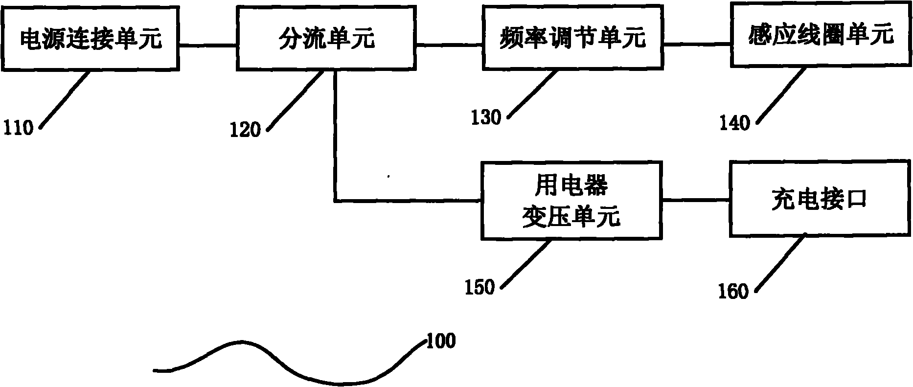
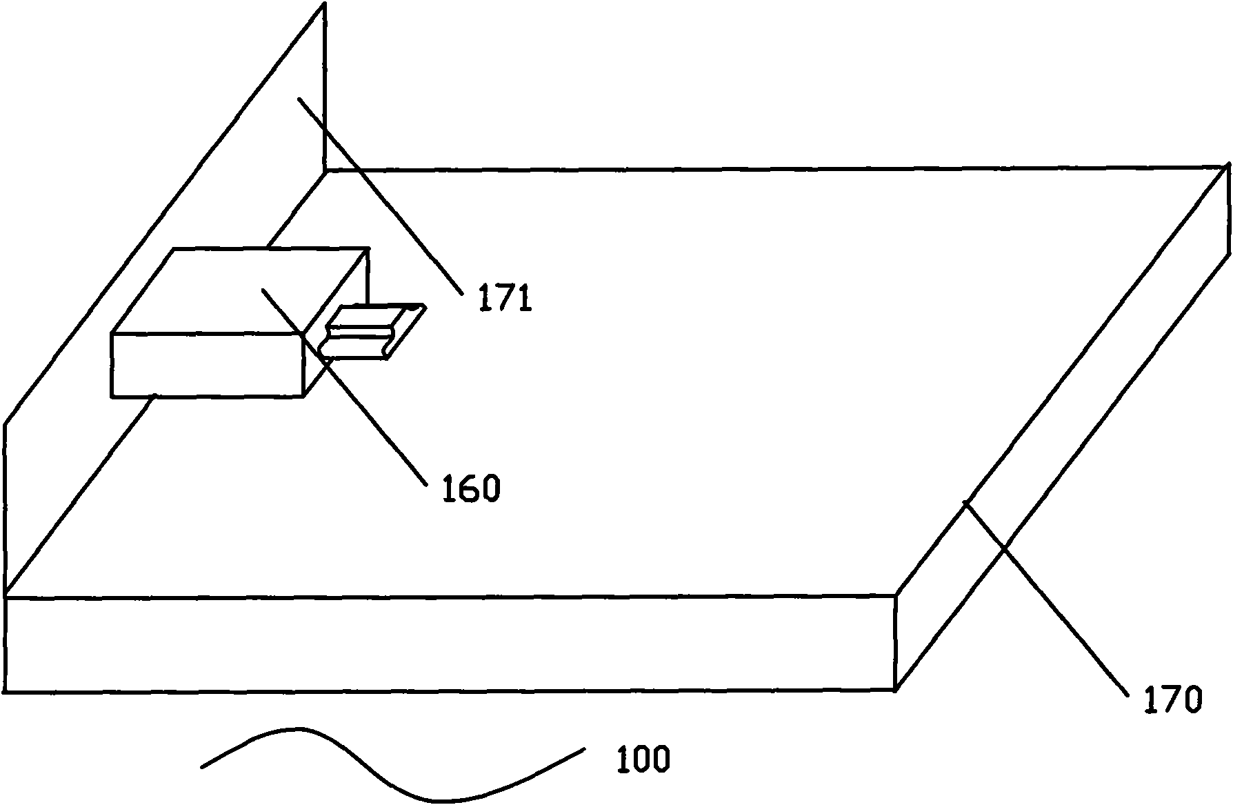
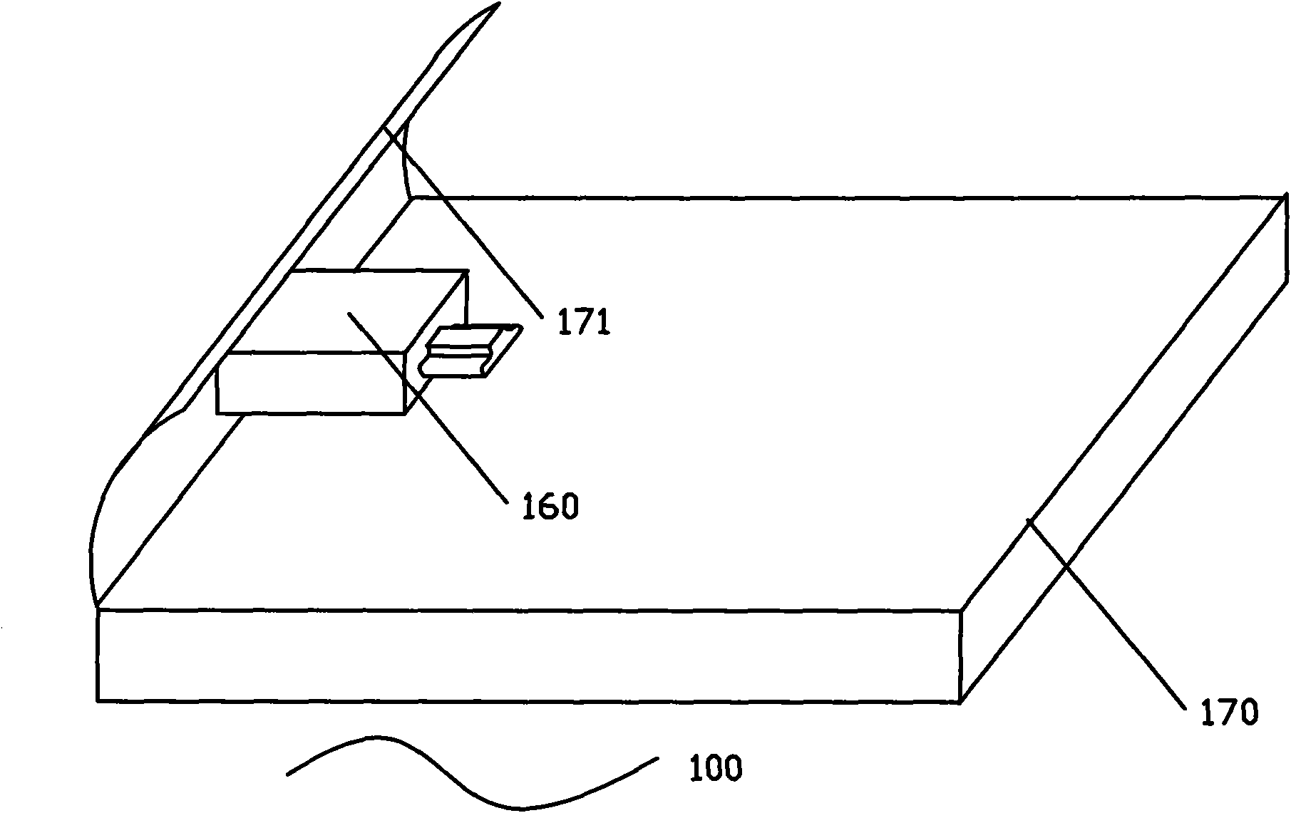
[0018] The wireless power supply device 100 provided by the present invention, such as figure 1 As shown, it includes a power supply connection unit 110 for connecting with a fixed power supply; a branching unit 120 connected with the power supply connection unit 110, and the branching unit 120 is used for dividing the current of the power supply into multiple branches connected in parallel; at least A frequency adjustment unit 130 and a main coil unit 140 connected to each other are arranged on one parallel branch, and an electrical transformer unit 150 and a charging interface 160 connected to each other are arranged on at least one parallel branch; the frequency adjustment unit 130 and the shunt unit 120 connected, the frequency adjustment unit 130 converts the received current into an alternating current of a specific frequenc...


PUM


Abstract

The invention discloses a wireless power supply device which comprises a power supply connecting unit for connecting a fixed power supply, a shunt unit connected with the power supply connecting unit, a frequency regulating unit, a main coil unit, an electric appliance transformation unit and a charging interface, wherein the shunt unit divides the current of the power supply into multiple branches connected in parallel; the frequency regulating unit and the main coil unit which are mutually connected are arranged on at least one branch connected in parallel; the electric appliance transformation unit and the charging interface mutually connected are arranged on at least one branch connected in parallel; the frequency regulating unit converts the received current into the alternating current with specific frequency and transmits the alternating current to an induction coil unit; the alternating current with the specific frequency in the induction coil unit generates a magnetic field which changes with the specific frequency; and the electric appliance transformation unit converts the received current into the direct current required by an electric appliance and transmits the converted direct current to the electric appliance through the charging interface. The wireless power supply device has the advantages that the charging efficiency of the electric appliance can be enhanced; multiple electric appliances are simultaneously charged by utilizing a fixed power supply socket; the use efficiency of the socket is enhanced; and the wireless power supply device can be used by users conveniently.

Description

technical field [0001] The invention relates to a power supply device, in particular to a wireless power supply device. Background technique [0002] In modern life, there are more and more types of electronic devices, and the charging interfaces of the electronic devices are different. Therefore, different chargers need to be equipped for various electronic devices. In this way, when the user needs to charge, he needs to select a suitable charger for different brands and models of electronic devices. Once a charger with a suitable interface is not found, the electronic device cannot be charged. At the same time, users need to buy chargers with multiple types of interfaces, which will cost a lot of money. They also need to be re-matched and selected from many chargers when using them, and the charging process of chargers and electronic devices needs to be plugged and unplugged many times. Cause damage to the interface of the electronic device, and further cause scrapping of...

Claims


Application Information

Patent Timeline
IPC IPC(8): H02J7/00H02J17/00H02J50/10
Inventor 林威廉
Owner AIGO DIGITAL TECHNOLOGY CO LTD
Learn More