Permanent magnet coupling speed regulator
A technology of permanent magnetic coupling and governor, applied in permanent magnetic clutches/brakes, electric brakes/clutches, asynchronous inductive clutches/brakes, etc., can solve the problems of high cost and achieve low cost, simple structure, shortened shaft effect on size
- Summary
- Abstract
- Description
- Claims
- Application Information
AI Technical Summary
Problems solved by technology
Method used
Image

Examples
Embodiment Construction
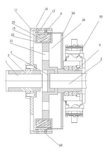
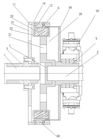
[0016] Refer to attached Figure 1~2 :
[0017] The input shaft 1 and the output shaft 2 are coaxial, and the cylindrical conductor rotor 10 is installed on the input shaft 1 through the flange 3 . The cylindrical conductor rotor body 11 is equipped with a cylindrical conductor piece 12 made of non-magnetic conductive material, and the bottom of the cylindrical conductor rotor body 11 is provided with a ventilation hole 15 .
[0018] The cylindrical permanent magnet rotor 20 is installed on the output shaft 2 through the clamping sleeve 4 , the vent hole 21 is provided at the web, and the permanent magnet seat 22 is set on the outer ring.
[0019] The cylindrical permanent magnet rotor 20 is installed in the cylindrical conductor rotor 10 separated by an air gap 60 therebetween.
[0020] The cylindrical magnetic isolation cover 30 is installed on the output shaft 2 through the moving sleeve 5, and is located between the cylindrical conductor rotor 10 and the cylindrical perm...
PUM
 Abstract
Description
Claims
Application Information