
Ratchet wrench

A ratchet wrench and wrench body technology, applied in the ratchet wrench field, can solve the problems of easy jamming, inability to use, limited use space and angle, etc., and achieve the effects of convenient use, easy manufacture and simple structure

Inactive Publication Date: 2011-05-04
WEIHAISHIWEILI TOP GRADE TOOL CO
View PDF10 Cites 7 Cited by
  • Summary
  • Abstract
  • Description
  • Claims
  • Application Information

AI Technical Summary

Problems solved by technology

When working, the wrench will be limited by the angle of the ratchet teeth from applying force to returning to the next force application position, and cannot stay in any position, so the use space and angle are limited, and it is not easy to use in a narrow space.
Because the ratchet is in surface contact, it is easy to get stuck when the torque is too large, causing the ratchet wrench to temporarily fail; in addition, the adjustment knob structure of the ratchet wrench is easy to disassemble, and parts such as reversing parts are easily damaged or lost, which will cause the wrench to be damaged. Not available

Method used


Image

  • Ratchet wrench
  • Ratchet wrench
  • Ratchet wrench

Examples


Embodiment Construction

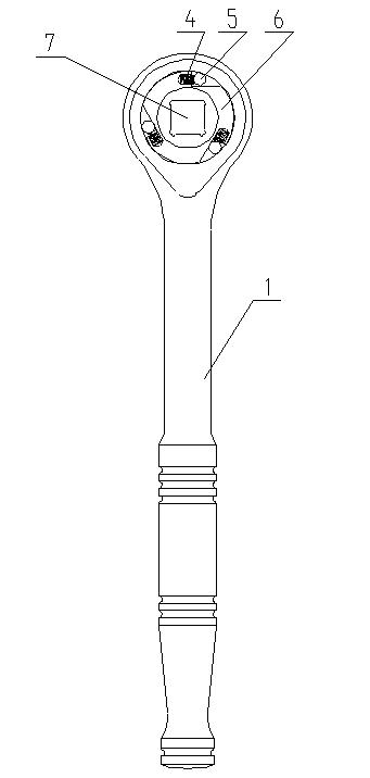
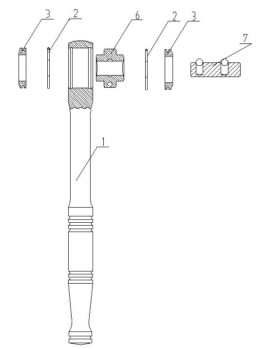
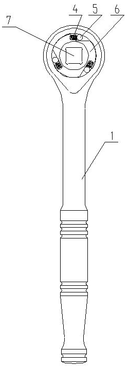
[0011] Such as figure 1 , figure 2 Shown: a ratchet wrench, one end of the handle 1 is connected to the head, the head is provided with a round hole, the inner edge of the round hole is provided with ring-shaped slots at both ends, and the round hole is provided with a rotatable wrench head 6 , the middle of the wrench head is provided with a square through hole, and the middle of one side of the through hole is provided with a groove. A round hole is arranged on the plane, a spring 4 is arranged in the round hole, a needle roller 5 is arranged in the gap, the wrench head is accommodated in the middle of the round hole, end caps 3 are arranged at both ends, and an annular groove is arranged on the end cap, A retaining ring 2 is arranged in the annular groove, and the retaining ring enters the ring-shaped draw-in groove on the inner edge of the circular hole to fix the end cover 3 . There are 3 breaches evenly distributed on the middle circumference of the pull body head, a ...


PUM


Abstract

The invention relates to the field of hardware hand tools, in particular to a ratchet wrench. The ratchet wrench is characterized in that one end of a hand shank is connected with a head part; the head part is provided with a round hole; two ends of the inner edge of the round hole are provided with annular slots; a rotatable wrench body head is arranged in the round hole; the middle of the wrench body head is provided with a square through hole; a groove is arranged in the middle of one side surface of the through hole; two ends of the wrench body head are of a circular truncated cone shape; a notch is arranged at the circumference of the wrench body head; the two planes of the notch are perpendicular with each other; one of the two planes is provided with a round hole, and a spring is arranged in the round hole; roller pins are arranged in the notch; the wrench body head is contained in the middle of the round hole; the two ends of the wrench body head are provided with end covers; the end covers are provided with annular grooves; the annular grooves are internally provided with spring retainers; the spring retainers enter into the annular slots of the inner edge of the round hole to fix the end covers; and a square rod is arranged in the square through hole. The ratchet wrench has the advantages that the structure is reasonable, the processing is simple, the assembly is convenient, the requirement on parts is lower as compared with similar products, the use is simple and convenient without space limitation, labor and time are saved, the working efficiency is high, and the reversing of the ratchet wrench is achieved through positive and negative faces so as to complete the fastening and looseness of screws.

Description

technical field [0001] The invention relates to the field of hand tools, in particular to a ratchet wrench. Background technique [0002] Existing ratchet wrench utilizes the teeth of a ratchet to engage with the rotating gear (or ratchet), which is located in the opening of the wrench head. The ratchet can define a shaped opening to mate directly with the nut or to accommodate a special insertion tool. When working, the wrench will be limited by the angle of the ratchet teeth from applying force to returning to the position of applying force next time, and cannot stay at any position, thus limiting the use space and angle, and it is not easy to use in a narrow space. Because the ratchet is in surface contact, it is easy to get stuck when the torque is too large, causing the ratchet wrench to temporarily fail; in addition, the adjustment knob structure of the ratchet wrench is easy to disassemble, and parts such as reversing parts are easily damaged or lost, which will caus...

Claims


Application Information

Patent Timeline
IPC IPC(8): B25B13/46
Inventor 刘永刚
Owner WEIHAISHIWEILI TOP GRADE TOOL CO
Learn More