Refuse collecting ship
A garbage collection and garbage technology, which is applied in water conservancy projects, cleaning of open water surfaces, construction, etc., can solve the problems of narrow water area, inability to guarantee the efficiency and effect of garbage cleaning, and inability to guarantee the safety of operators, so as to achieve low energy consumption of the device , Garbage collection and storage capacity increase, the effect of improving work efficiency
Inactive Publication Date: 2011-05-04
浙江机电职业技术学院
View PDF6 Cites 14 Cited by
- Summary
- Abstract
- Description
- Claims
- Application Information
AI Technical Summary
Problems solved by technology
At present, the cleaning of garbage in water basically adopts the method of manual fishing. However, manual cleaning can neither guarantee the efficiency and effect of cleaning garbage, nor can it guarantee the safety of operators; The water area is narrow, and only garbage in the area touched by its tool can be fished
Method used
View moreImage
Smart ImageViewing Examples
Examples
Embodiment 2
Login to View More PUM
 Abstract
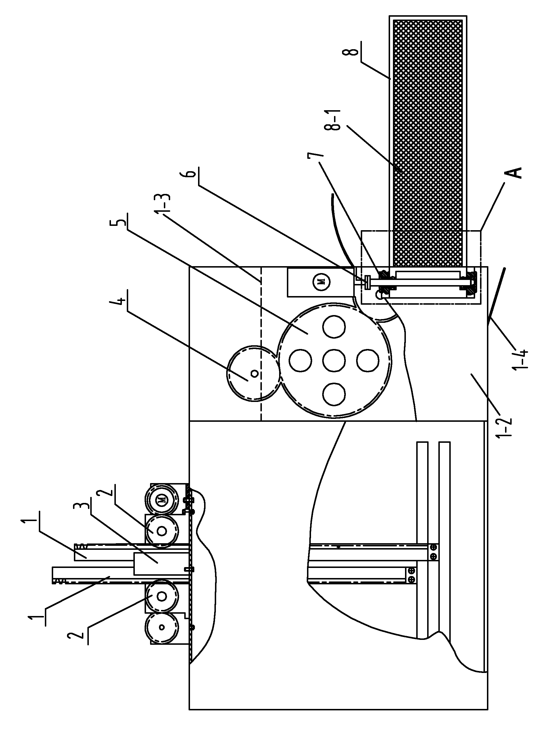
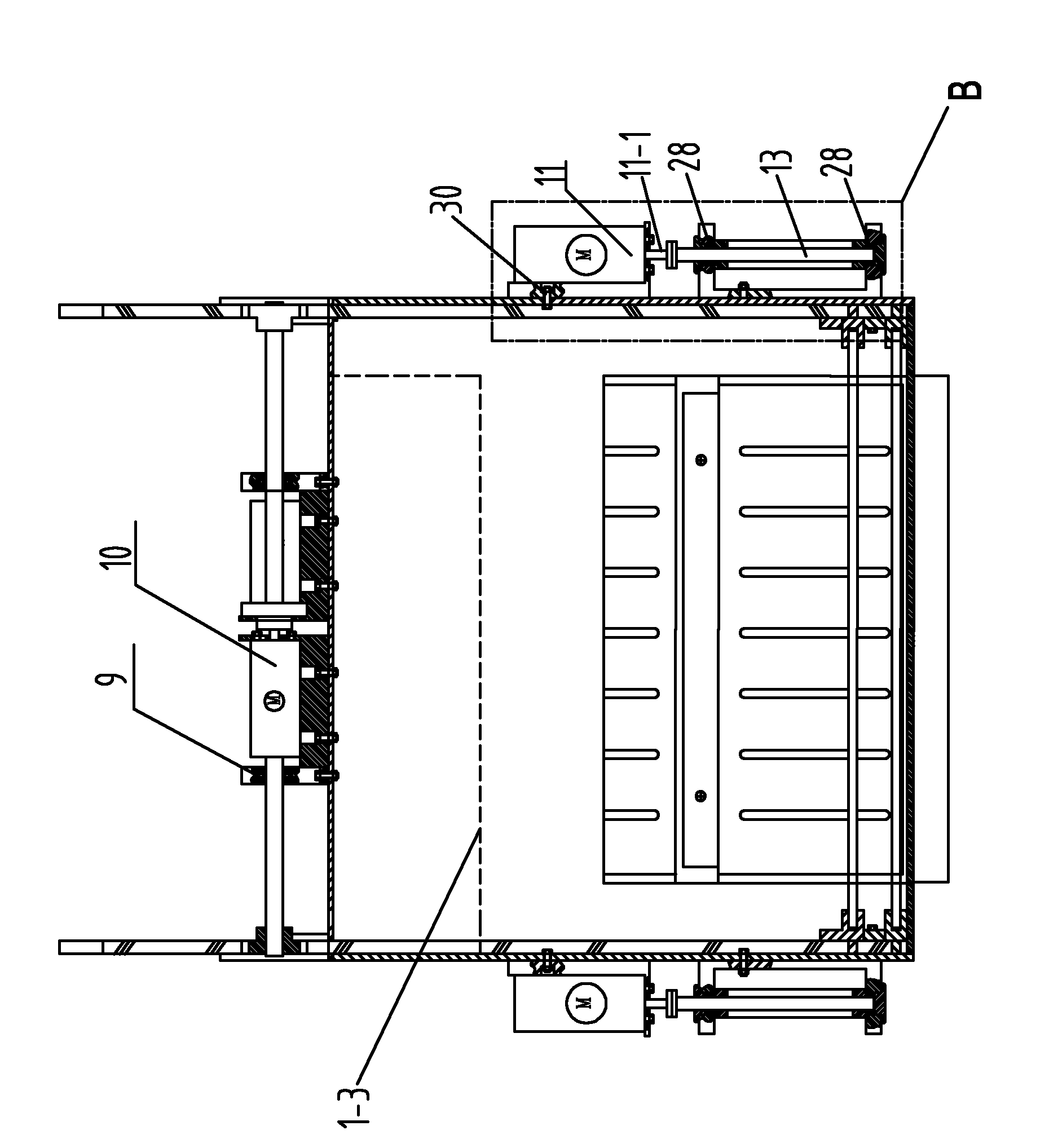
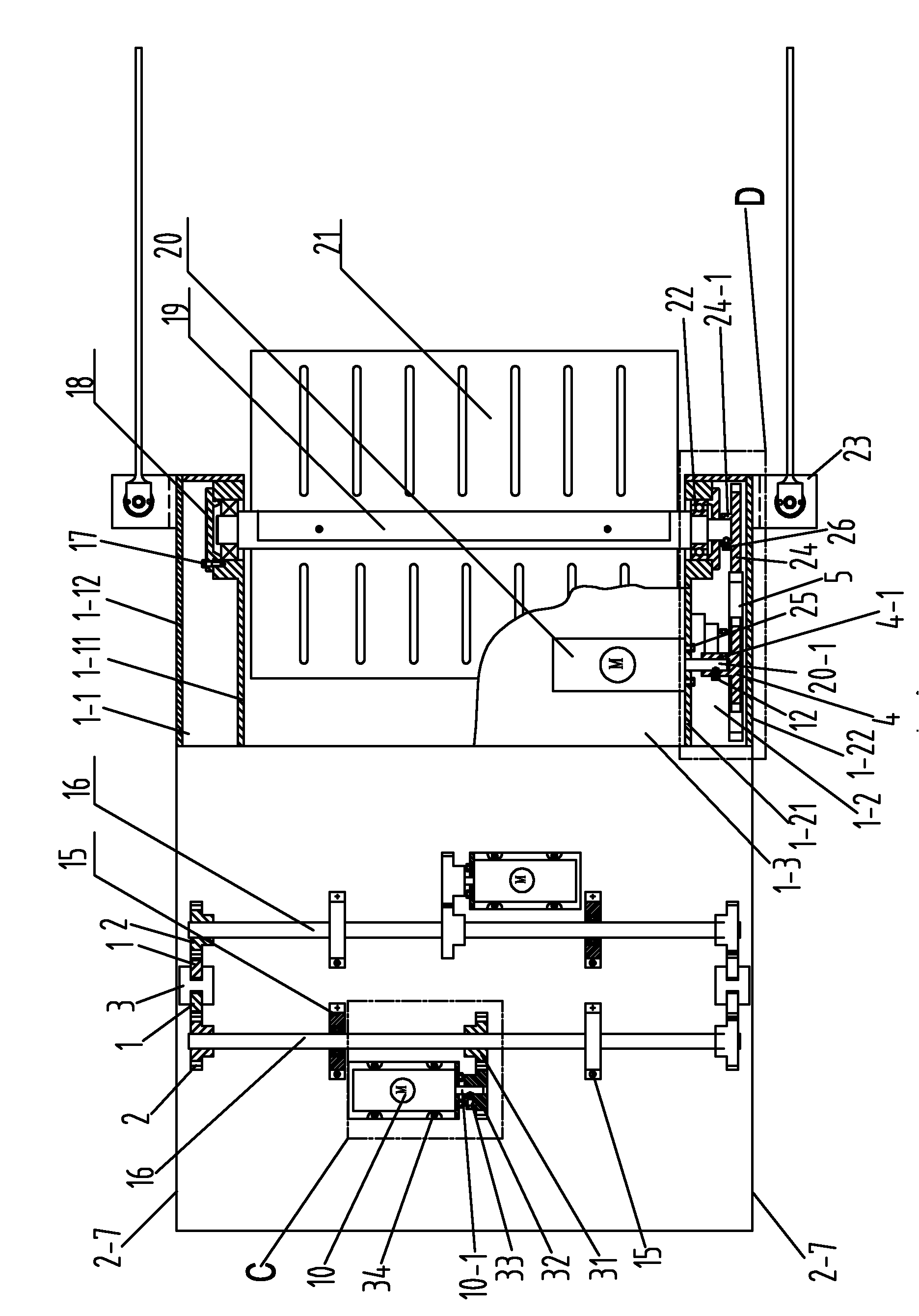
The invention discloses a refuse collecting ship, which comprises a refuse collecting device and a refuse storing device, wherein the refuse collecting device comprises a tank body of which the middle is provided with a through hole; a motor is arranged above the tank body, the output shaft of the motor is linked with an impeller shaft, and the impeller shaft is arranged in the tank body and traverses the tank body; a plurality of blades are fixedly arranged on the outer circumference of the impeller shaft; an accommodating area is formed in the refuse storing device and is provided with a refuse inlet; a refuse compressing mechanism is arranged in the refuse storing device and drives a compressing plate to act; the refuse storing device is fixedly connected with the refuse collecting device; and the refuse inlet of the refuse storing device corresponds to an outlet of the through hole in the middle of the tan body. When used, the refuse collecting ship can be arranged on the conventional ship, and the conventional ship drives the refuse collecting ship to move in water so as to clean refuse in the water; and the refuse collecting ship also can work independently and is provided with a floating device to float on water surface and clean the refuse in the water simultaneously.
Description
technical field [0001] The invention belongs to the technical field of manufacturing garbage cleaning devices in water, and in particular relates to a garbage collection ship. Background technique [0002] Due to the lack of awareness of environmental protection of some people, they throw garbage into the water at will and a large amount of floating garbage on the water surface produced by the natural environment, resulting in more and more garbage in the water, and the water pollution is becoming more and more serious. Because the water body can flow, when the polluted water flows to other places, the pollutants will be taken to other places. It can be said that the harm of water body pollution is greater than that of ground pollution. Therefore, it is more urgent and important to clean up the garbage on the water than to clean up the garbage on the land. At present, the cleaning of garbage in water basically adopts the method of manual fishing. However, manual cleaning ...
Claims
Login to View More Application Information
Patent Timeline
 Patent Type & Authority Applications(China)
IPC IPC(8): E02B15/10
Inventor 陈晓英颜关祥施程适闻绍华倪寅乾陈铭铭
Owner 浙江机电职业技术学院
Features
- R&D
- Intellectual Property
- Life Sciences
- Materials
- Tech Scout
- Unparalleled Data Quality
- Higher Quality Content
- 60% Fewer Hallucinations
Learn More Browse by: Latest US Patents, China's latest patents, Technical Efficacy Thesaurus, Application Domain, Technology Topic, Popular Technical Reports.
© 2025 PatSnap. All rights reserved.Legal|Privacy policy|Modern Slavery Act Transparency Statement|Sitemap|About US| Contact US: help@patsnap.com


