
Spiral fluid turbine pump

A technology of screw type and turbo pumps, applied in the direction of rotary piston pumps, rotary piston machines, pumps, etc., can solve the problems of fluid working medium pulsation, etc., and achieve the goal of promoting energy saving, resource saving, and long service life Effect

Inactive Publication Date: 2011-05-04
王跃
View PDF1 Cites 2 Cited by
  • Summary
  • Abstract
  • Description
  • Claims
  • Application Information

AI Technical Summary

Problems solved by technology

According to the technical description of the fluid machinery, the reversible operation or combined use of the fluid working medium and the rotor of the machine can be realized, but this technology also has the pulsation defect of the fluid working medium

Method used


Image

  • Spiral fluid turbine pump
  • Spiral fluid turbine pump
  • Spiral fluid turbine pump

Examples


Embodiment 1

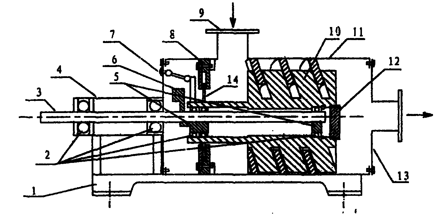
[0026] Screw type fluid turbine pump single screw machine ( figure 1 ), through at least one helicoidal rotor (10) moving in a translational manner in the helical stator (11), work is done on the fluid working medium in the cavity so that the fluid working medium is continuously discharged from the inlet to the outlet or reversed with the fluid working medium The movement mode continuously works on the helical rotor to output power. The structure consists of a machine base (1) connected with a spiral stator (11), a bearing seat (4), a rotor locking device (7), a sealing plate (12), and a power shaft (3) installed on the machine base (1). There are bearings (2), eccentric wheel (5) and balance iron (6) on the upper sleeve, and the spiral rotor (10) is equipped with bearing (2) and fits with the eccentric wheel (5), and is also connected with a sealing device (8) , The rotor locking device (7) is placed in the cylinder of the spiral stator (11), and the spiral stator (11) is al...

Embodiment 2

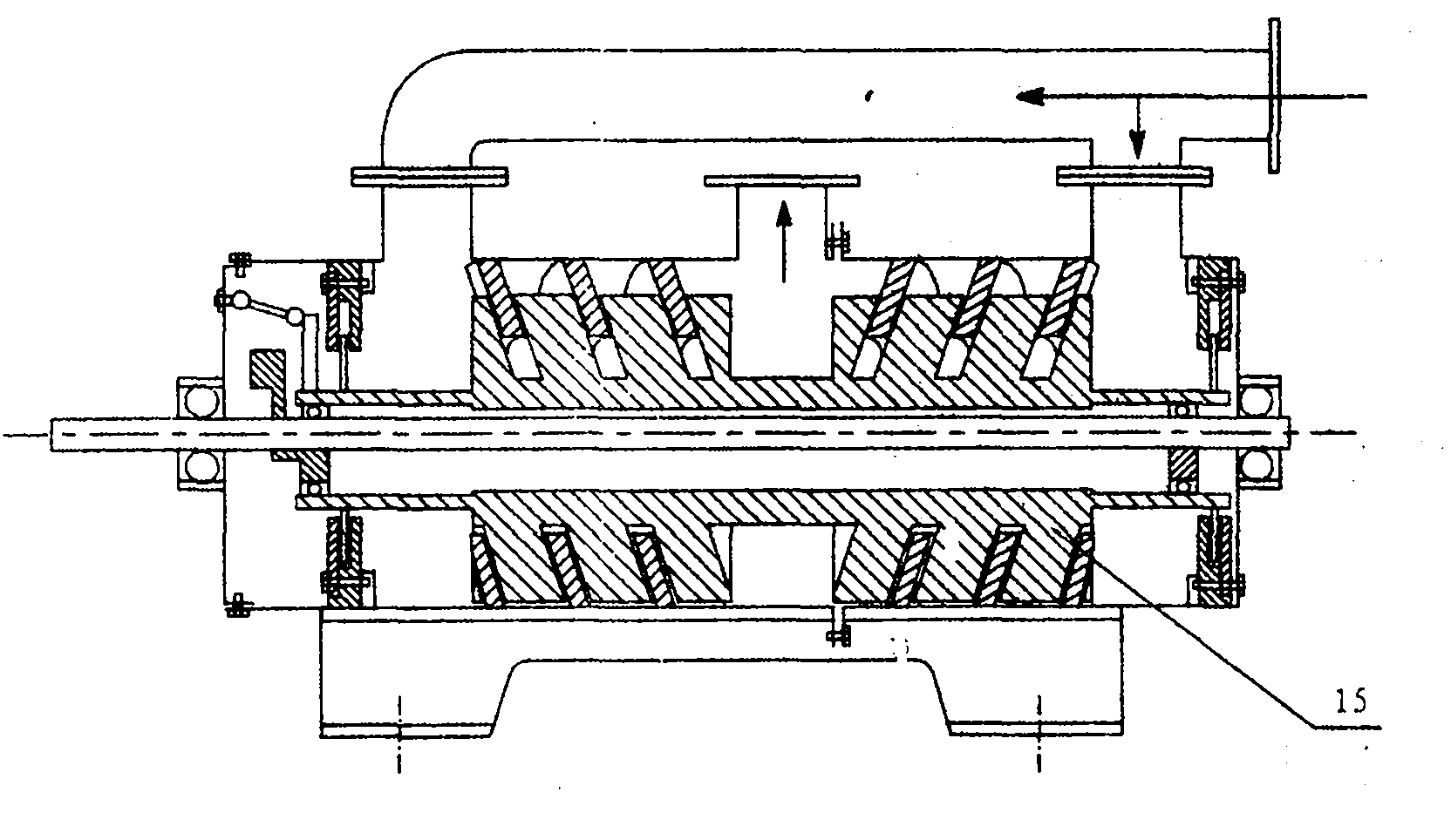
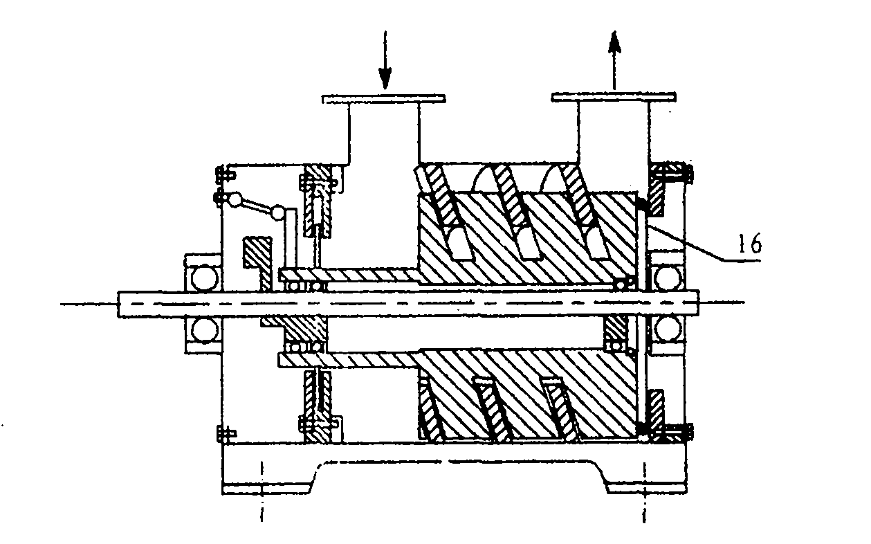
[0034] Helical fluid turbine pump twin-screw machine ( figure 2 ) is an extended model of the basic type of single-screw machine, and its rotor and stator can be two coaxial counter-rotating rotors with two positive and negative rotations matching the stator double-helix structure (15), the purpose of which is to In order to balance the axial thrust, the end cover (16) of the double-screw machine is also embedded with a bearing and receives the power shaft. This model is simple and compact, with good balance and higher efficiency. The same content as the foregoing embodiment 1 will not be repeated here.


PUM


Abstract

The invention relates to a fluid machine, in particular to a spiral fluid turbine pump. A mechanical spiral rotor moves in a spiral stator, and applies work to a fluid working medium in a cavity so that the fluid working medium is continuously discharged or the spiral rotor is continuously acted in a reverse motion mode of the fluid working medium to output power. The spiral fluid turbine pump of the technology can be used as fluid pump equipment or fluid motor equipment, and can be designed into large, small and micro machine series; and the equipment of the technology has simple structure, good reliability, continuity and pulsation of the working medium, low noise and high efficiency, and can be used for functional conversion of gas and liquid, energy conservation, emission reduction, production and the like.

Description

technical field [0001] The invention relates to a fluid machine, in particular to a machine in which a helical rotor moves in a helical stator, and works on the fluid working medium in the cavity to discharge the fluid working medium continuously or reversely move the fluid working medium. A helical fluid turbine pump in which the helical rotor continuously performs work and outputs power. Background technique [0002] The scroll compressor and scroll vacuum pump in the prior art use the involute scroll rotor to move between the involute scroll stators, so that the working medium gas in the scroll cavity is discharged from the outside to the center, and the continuous completion Inhalation, compression, exhaust process. However, this technology is generally only applicable to gaseous working fluids, and there are defects in the pulsation of fluid working fluids and limitations in the scope of application. [0003] The so-called kneading fluid mechanical technology of CN200...

Claims


Application Information

Patent Timeline
Patent Type & Authority Applications(China)
IPC IPC(8): F04C2/16
Inventor 王跃
Owner 王跃
Learn More