Scroll compressor

A scroll compressor and scroll technology, applied in the direction of rotary piston machines, rotary piston pumps, mechanical equipment, etc., can solve the problems of increased discharge loss and cost increase, and achieve reduced discharge loss, less oil discharge, cost reduction effect

Inactive Publication Date: 2011-05-04
PANASONIC CORP
View PDF8 Cites 16 Cited by
  • Summary
  • Abstract
  • Description
  • Claims
  • Application Information

AI Technical Summary

Problems solved by technology

[0016] In the conventional structure, the discharge hole and the three check valves on each bypass path were distributed, causing many problems, such as: increased discharge loss due to the interference of the outflow gas from the check valve; covering the check valve The cost increases due to the increase in the size of the isolation parts, etc., but with this structure, not only can the fluid be reliably bypassed to the discharge chamber during excessive compression operation to reduce the dis

Method used


Image

  • Scroll compressor
  • Scroll compressor
  • Scroll compressor

Examples


Embodiment 1

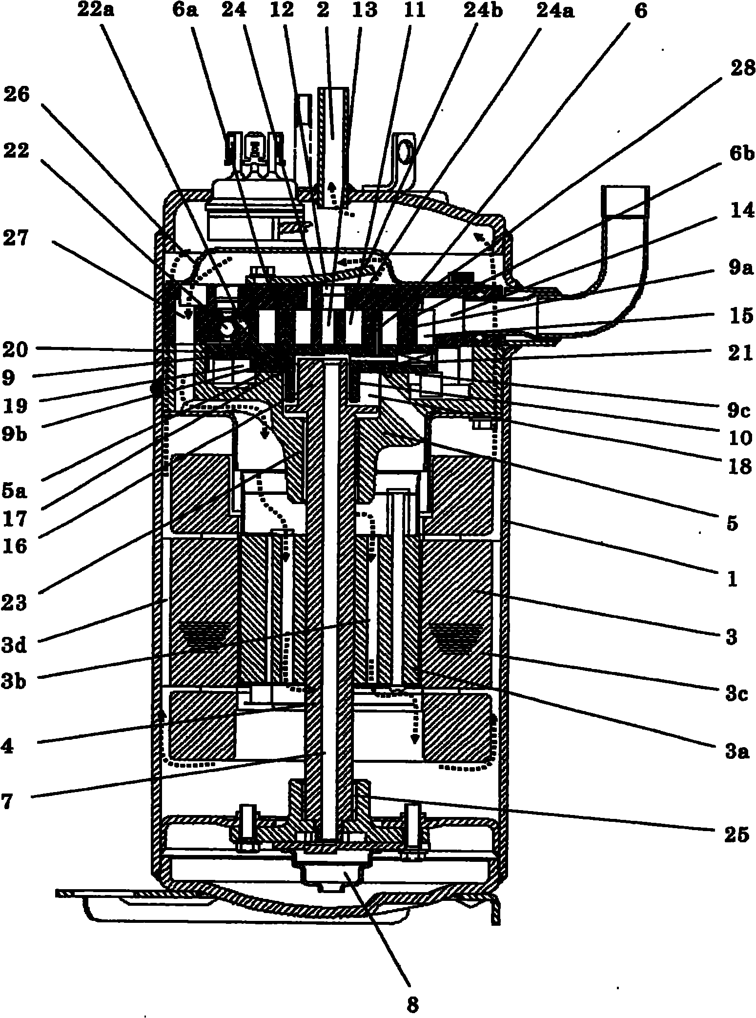
[0050] figure 1 It is a longitudinal sectional view of the scroll compressor according to Embodiment 1 of the present invention. exist figure 1 Among them, the entire interior of the iron airtight container 1 is a high-pressure environment communicated with the discharge pipe 2, an electric motor 3 is arranged in its central part, and a compression mechanism is arranged on the upper part, and the main body frame 5 of the compression mechanism is fixed on the airtight container 1 One end of the crankshaft 4 of the rotor 3a of the motor 3 is supported on the body frame 5, and a fixed scroll 6 is installed on the body frame 5.

[0051] An axial oil passage 7 is provided on the crankshaft 4 , one end of which leads to the oil supply pump device 8 , and the other end eventually leads to the eccentric bearing 10 of the movable scroll 9 . The movable scroll 9, which meshes with the fixed scroll 6 and constitutes the compression chamber 11, is composed of a rotating mirror plate 9...

Embodiment 2

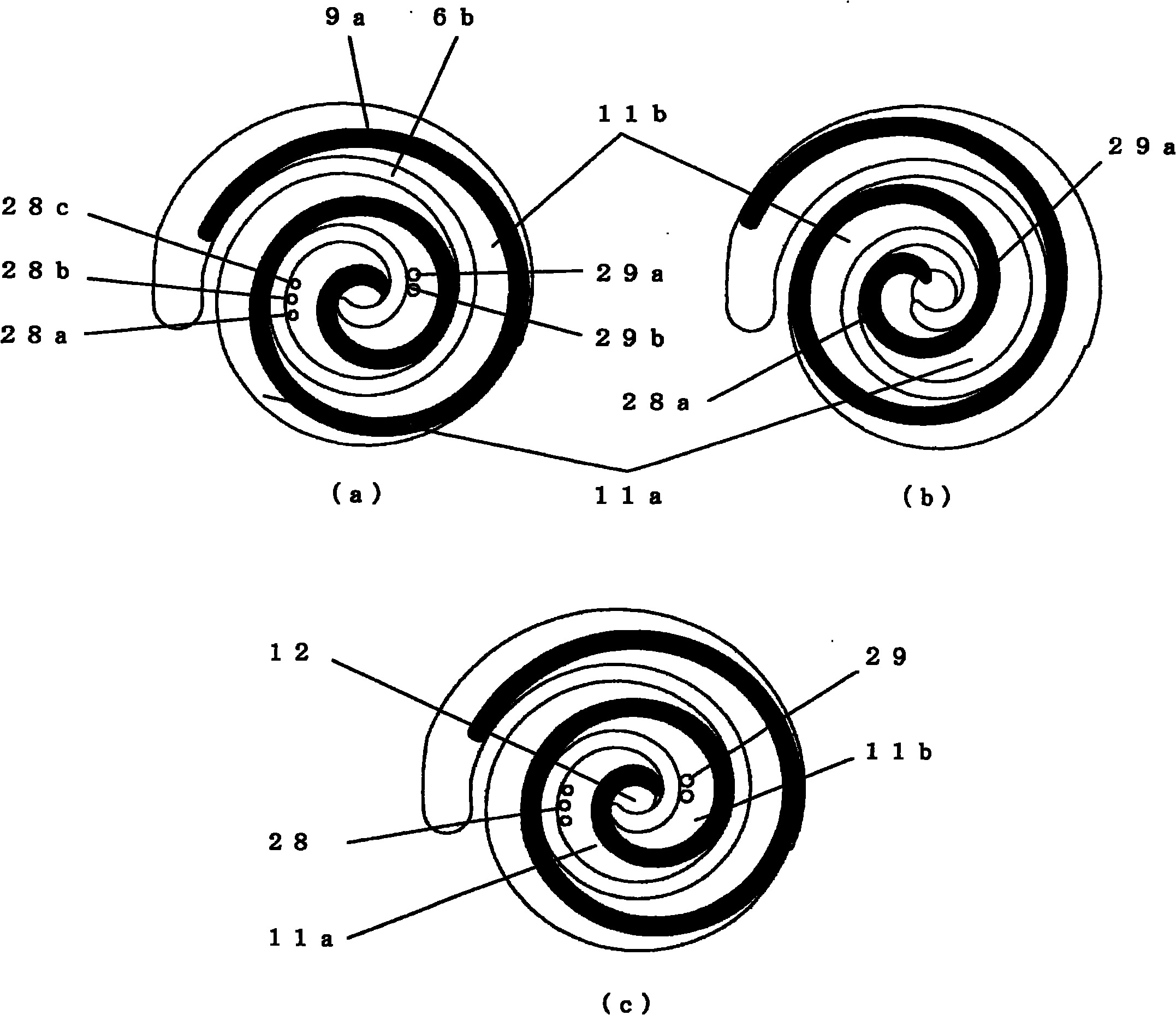
[0075] Figure 6 It is a transverse cross-sectional view of the compression mechanism part in Embodiment 2 of the present invention. The fixed scroll 6 is provided with a first bypass passage 28 composed of three holes 28a, 28b, 28c and a second bypass passage 29 composed of two holes 29a, 29b. Since the second bypass passage 29 Compared with the first bypass path 28, the number of holes is less and the area of ​​the holes is larger. Therefore, as in Embodiment 1, the check valves of each bypass path 28, 29 and the discharge hole 12 can be arranged neatly and miniaturization.

[0076] At the same time, the center-to-center distance of the holes of the second bypass path 29 is set larger than that of the first bypass path 28 to ensure that the second bypass path 29 is opened in the second compression chamber 11b for as long as possible. , it can correspond to the compression ratio under a wide range of operating conditions, and reduce the discharge loss caused by excessive co...

Embodiment 3

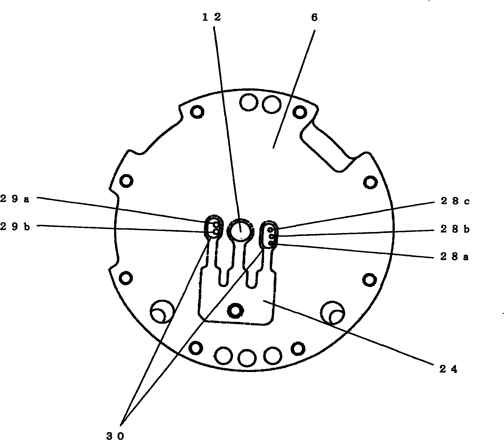
[0080] Figure 7 It is a transverse sectional view of the compression mechanism part in Embodiment 3 of the present invention. The fixed scroll 6 is provided with a first bypass passage 28 composed of two holes 28a, 28b and a second bypass passage 29 composed of a hole 29a having a larger area than these holes 28a, 28b. 1 The closed volume of the compression chamber 11a is larger than that of the second compression chamber 11b, which is an asymmetric scroll structure. The total cross-sectional area of ​​the first bypass path 28 is set to be larger than the total cross-sectional area of ​​the second bypass path 29. bigger. Therefore, similar to Embodiment 1, the respective bypass passages 28, 29 and the check valves of the discharge hole 12 can be neatly arranged and miniaturized, and appropriate bypass valves can be set according to the closed volumes of the respective compression chambers 11a, 11b. The flow path cross-sectional area of ​​the paths 28, 29 is reduced, thereby...


PUM


Abstract

The present invention provides a scroll compressor in which check valves are arranged neatly and miniaturized for realizing high efficiency and low cost. In the scroll compressor, a central part is provided with an exhaust path which is communicated with an exhaust chamber (13); a first compression chamber (11a) and a second compression chamber (11b) are respectively provided with a first bypass path (28) and a second bypass path (29) which are communicated with the exhaust chamber in the middle part of compression. The first bypass path and the second bypass path are respectively composed of at least one hole. The exhaust path and each bypass path are respectively provided with a check valve (24). The bypass path of the compression chamber at the outer wall side of a scroll has a smaller number of the holes and larger area of the hole compared with a bypass path of the compression chamber at the inner wall side of the scroll. The holes on the first bypass path and the second bypass path are set parallelly as possible. The check valves are arranged neatly for obtaining high compactness, small size and cost reduction. The coexistence of high efficiency and low cost is obtained.

Description

technical field [0001] The present invention relates to a scroll compressor used in air conditioners, refrigerators, blowers, water heaters and other machines. Background technique [0002] In the existing scroll compressor, the fixed scroll and the movable scroll, which form scroll wraps on the mirror plate, mesh with each other to form a plurality of compression chambers, and a crankshaft with an eccentric portion is connected to the movable scroll. The coupling prevents rotation and performs rotational movement, and continuously compresses while gradually reducing the volume toward the center. The existing scroll compressor has the following characteristics. The suction chamber is located at the outer periphery of the scroll forming the compression space, and the discharge hole is provided at the center of the scroll. The volume at the end of suction and the volume at the end of compression are determined. Set the compression ratio to be constant. Therefore, for an oper...

Claims


Application Information

Patent Timeline
IPC IPC(8): F04C18/02
Inventor 吉田裕文森本敬池田明二上义幸鶸田晃作田淳
Owner PANASONIC CORP
Why Eureka
Try Eureka