Lamp

A lamp and lamp body technology, which is applied in the direction of anti-loss measures of lighting devices, lighting devices, cooling/heating devices of lighting devices, etc., can solve the problems of poor safety and dust entering the interior of the lamp housing, etc., to improve the decorative effect Effect

Inactive Publication Date: 2011-05-04
SUNONWEALTH ELECTRIC MACHINE IND
View PDF0 Cites 11 Cited by
  • Summary
  • Abstract
  • Description
  • Claims
  • Application Information

AI Technical Summary

Problems solved by technology

[0006] The purpose of the present invention is to provide a lamp, which can prevent users from viewing or touching the relevant components inside the lamp in the horizontal direct viewing

Method used


Image

  • Lamp
  • Lamp
  • Lamp

Examples


Embodiment Construction

[0042] In order to make the above-mentioned and other objects, features and advantages of the present invention more comprehensible, the preferred embodiments of the present invention are specifically cited below, together with the accompanying drawings, as follows:

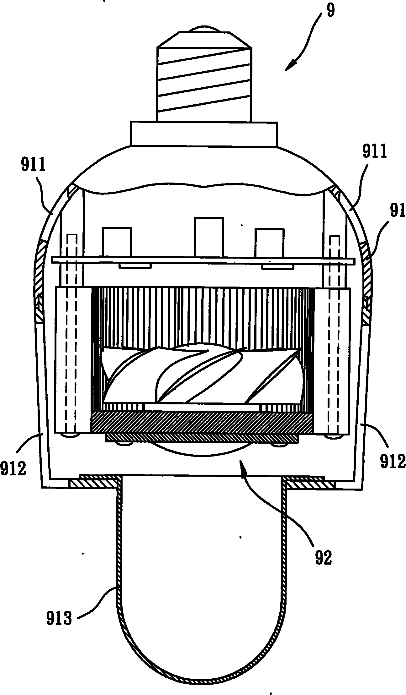
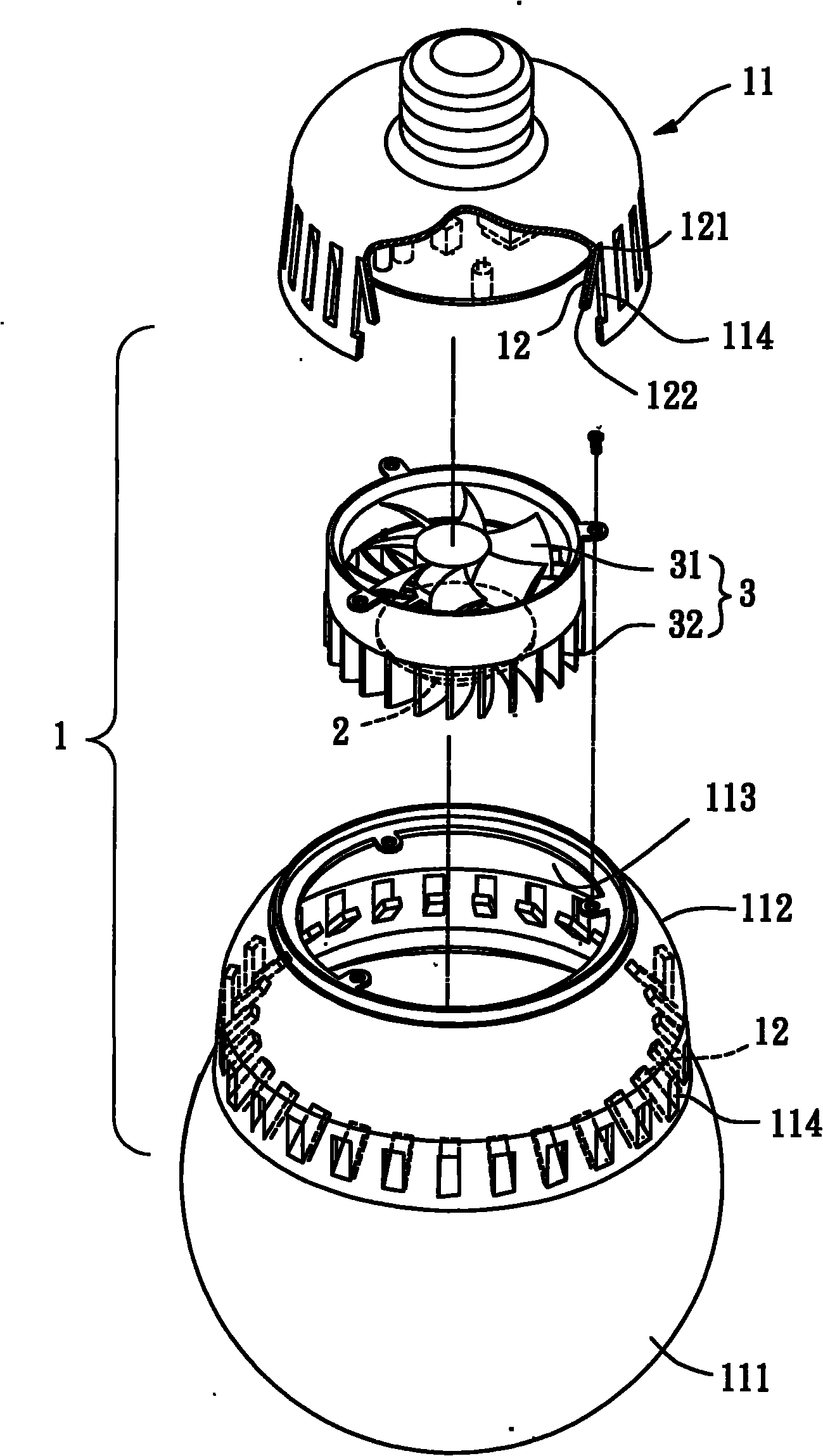
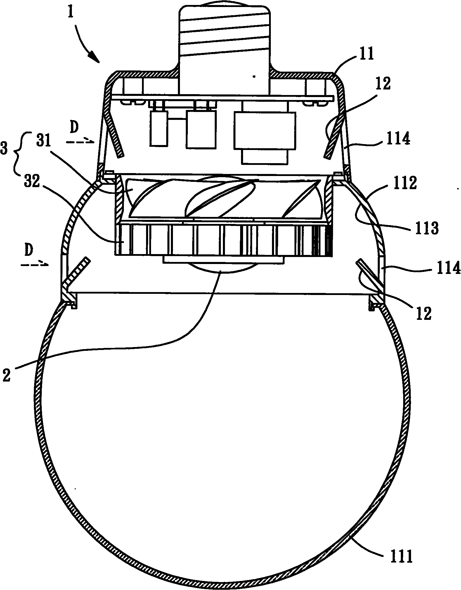
[0043] Please refer to figure 2 and 3 As shown, the lamp of the first embodiment of the present invention includes a lamp body 1 and a light emitting module 2 . The lamp body 1 can be formed by a single shell or several shells; the light-emitting module 2 is integrated inside the lamp body 1; thereby, the light-emitting module 2 can project light to the external space through the lamp body 1 to provide lighting function.

[0044] The lamp body 1 includes a shell 11 and several blocking pieces 12 . In the embodiment shown in the figure, the shell 11 is composed of several shell parts paired with each other; one end of the shell 11 is provided with a light-transmitting portion 111, and the shell 11 has an outer...


PUM


Abstract

The invention relates to a lamp which comprises a lamp body and a light emitting module, wherein the lamp body is provided with a plurality of vent holes; and the light emitting module is combined with the inside of the lamp body. By utilizing structure design such as a baffle, dislocation mode, shield part and the like, the user can not easily see or contact the related components inside the lamp in the horizontal direct vision direction by the vent holes, thereby enhancing the decorative effect, safety and dust shielding function of the lamp.

Description

technical field [0001] The invention relates to a lamp, in particular to a lamp which has lighting and decoration functions, has high safety, and can block dust from entering the interior of the lamp housing. Background technique [0002] Existing lamps, such as China Taiwan Announcement No. M339636 "LED Lamp Heat Dissipation Structure (1)" new patent case. The lamp has a lamp body, and the lamp body is provided with several light-emitting diodes and a lampshade, and the light-emitting diodes can project light to the external space through the lampshade after being powered on; in addition, several heat sinks are protruded from the lamp body, thereby, When each of the light emitting diodes generates heat due to electrification, each of the cooling fins can be used to assist the light emitting diodes to dissipate heat. [0003] However, although the heat sink of the existing lamp can absorb the heat generated by the light-emitting diodes after being powered on, because the la...

Claims


Application Information

Patent Timeline
IPC IPC(8): F21S2/00F21V15/02F21V29/00F21V29/02F21V29/67F21V29/74F21V29/83
Inventor 洪银树宫原雅晴锺志豪
Owner SUNONWEALTH ELECTRIC MACHINE IND
Why Eureka
Try Eureka