Electronic apparatus and liquid crystal display device for irradiating ultraviolet ray to luminescent layer

a liquid crystal display device and ultraviolet light technology, applied in the field of electronic devices, can solve the problems of insufficient light saving, inability to emit light,

Inactive Publication Date: 2004-10-19
CASIO COMPUTER CO LTD
View PDF10 Cites 53 Cited by
  • Summary
  • Abstract
  • Description
  • Claims
  • Application Information

AI Technical Summary

Benefits of technology

Further, another object of the present invention is to obtain an electronic apparatus or a liquid crystal display device which achieves a backlight function at a luminescent layer and has an excellent decoration property.
Moreover, a further object of the present invention is to irradiate a light in the ultraviolet range emitted from the ultraviolet ray-emitting portion to the luminescent layer efficiently without damaging the light.

Problems solved by technology

However, the phosphorescent portion cannot emit a light when a user desires, or cannot emit a light for a long time.
However, in the former wrist watch, there is a problem that the energy of the light cannot be saved sufficiently in the phosphorescent portion provided in the dial or the hands since the light from the light source becomes weak.
Further, in the latter wrist watch, although the energy of the light can be saved sufficiently in the phosphorescent portion in the dial or the hands if the light from the light source is made strong, there is no meaning for providing the phosphorescent portion since the upper side of the dial becomes bright by the light from the light source.
Moreover, there is a problem that the disposed structure becomes complicated and the light source cannot be disposed easily since it is required to dispose the light source so that the light source does not obstruct the dial or the hands and is not broken by a shock, when the light source is disposed.

Method used


Image

  • Electronic apparatus and liquid crystal display device for irradiating ultraviolet ray to luminescent layer
  • Electronic apparatus and liquid crystal display device for irradiating ultraviolet ray to luminescent layer
  • Electronic apparatus and liquid crystal display device for irradiating ultraviolet ray to luminescent layer

Examples


first embodiment

[First Embodiment]

Hereinafter, a first embodiment in which the present invention is applied to a wrist watch will be explained with reference to FIGS. 1 to 7.

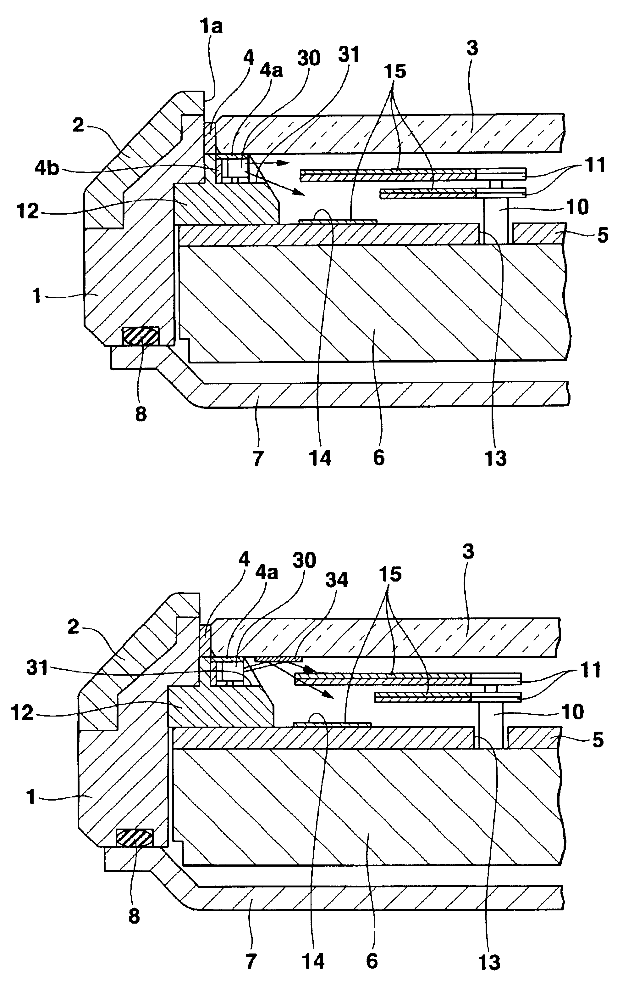
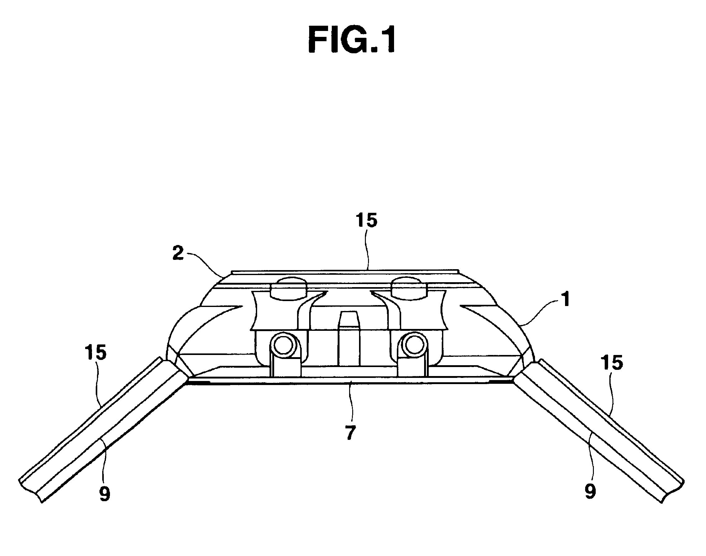
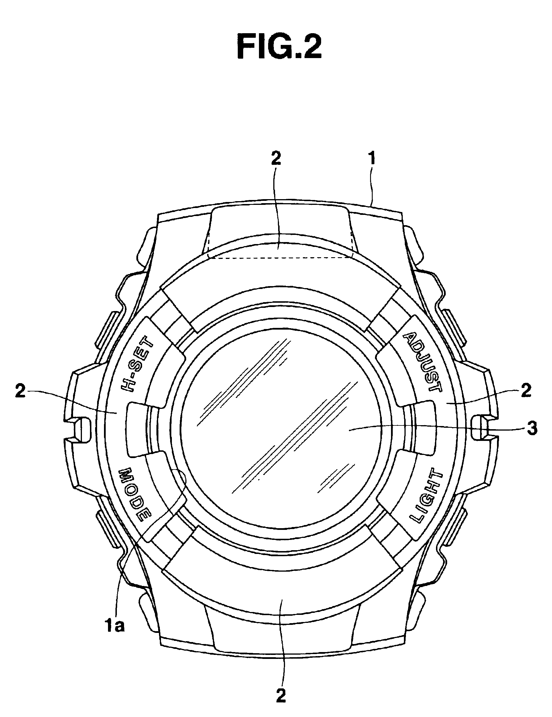
FIG. 1 is a side view showing the wrist watch, a portion of which is omitted. FIG. 2 is an enlarged plan view showing a wrist watch case which is the wrist watch in FIG. 1 without watch bands. FIG. 3 is an enlarged cross-sectional view showing a principal of an inner structure of the wrist watch case.

The wrist watch comprises a wrist watch case 1 as an apparatus case. As shown in FIG. 2, bezels 2 are provided on outer periphery in the upper portion of the wrist watch case 1. As shown in FIG. 3, a watch glass 3 is mounted on an aperture portion 1a provided in the center in the upper portion of the wrist watch case 1 via a packing 4. Further, in the inside of the wrist watch case 1, a dial 5 and a watch module 6 are contained. On the lower surface of the wrist watch case 1, a rear cover 7 is attached via a waterproof ring 8. More...

second embodiment

[Second Embodiment]

Next, a second embodiment in which the present invention is applied to a wrist watch will be explained with reference to FIG. 12. The same reference numerals are attached to the same elements as the first embodiment and each of its modified examples shown in FIGS. 1 to 11 in order to explain the second embodiment.

The wrist watch has a structure that a transparent luminescent layer 20 having a laminated structure is provided on the upper surface of the dial 5. The other structures of the wrist watch is approximately the same as those of the first embodiment.

That is, the transparent luminescent layer 20 has a structure that a first to third luminescent films 21 to 23 which emit light with color dissimilar to each other by reacting to the light in the ultraviolet range are laminated. The transparent luminescent layer 20 is provided on predetermined points (for example, in mark portions) and / or on the upper surface of the time indices 14, in the upper surface of a dia...

third embodiment

[Third Embodiment]

Next, a third embodiment in which the present invention is applied to a wrist watch will be explained with reference to FIGS. 13 and 14. In this case, the same reference numerals are also attached to the same elements as the first embodiment and each of its modified examples shown in FIGS. 1 to 11 in order to explain the third embodiment.

The wrist watch has a structure that a transparent luminescent layer 25 in which dot-like luminescent portions 26 are arranged is provided on the upper surface of a dial 5. The other structures of the wrist watch is approximately the same as those of the first embodiment.

That is, the transparent luminescent layer 25 has a structure that numbers of dot-like luminescent portions 26 are arranged in dot-like by printing.

In this case, the dot-like luminescent portions 26 emit lights with dissimilar colors by reacting to the light in the ultraviolet range (with a wavelength between 350 and 420 nm), and are in a transparent state when the...


PUM

PropertyMeasurementUnit
wavelengthaaaaaaaaaa

Abstract

An ultraviolet ray-emitting element is provided in a frame-like member disposed between an apparatus module and an apparatus case by corresponding to a peripheral portion of a protective glass. A light in an ultraviolet range from the ultraviolet ray-emitting element is irradiated between the module and the protective glass. A luminescent layer to which an ultraviolet ray is irradiated emits a light.

Description

1. Field of the InventionThe present invention relates to an electronic apparatus, such as a wrist watch, a portable telephone or the like, and a liquid crystal display device.2. Description of Related ArtFor example, there is a wrist watch having a phosphorescent portion provided by applying a phosphorescent paint, such as a luminous paint or the like, partially to timepiece parts, such as a dial, hands and the like. The phosphorescent portion of the wrist watch saves energy by receiving an external light in a bright place, and the wrist watch emits a light in a dark place by the energy saved by the phosphorescent portion.In such a wrist watch, the phosphorescent portion emits a light for a short time in a dark place, so that time can be recognized. However, the phosphorescent portion cannot emit a light when a user desires, or cannot emit a light for a long time.Therefore, in earlier technology, it is proposed that the phosphorescent portion emits a light when a user desires by us...

Claims


Application Information

Patent Timeline
Patent Type & Authority Patents(United States)
IPC IPC(8): G02F1/13G02F1/1335G04G9/00H04M1/22H04M1/02G02F1/13357G04B19/32
CPCG02F1/133617H04M1/22G04G9/0041H04M1/0283G02F1/1335
Inventor UENO, MASATOHIRANO, TADAOMACHIDA, SHYUICHIUSUI, NORIHISA
Owner CASIO COMPUTER CO LTD
Why Eureka
Try Eureka