Line filter

A filter and circuit technology, applied in the manufacturing of circuits, inductors, coils, etc., can solve the problems of reducing height, unable to perform correct positioning, unable to fully ensure insulation distance, etc., to achieve the effect of ensuring insulation distance

Inactive Publication Date: 2011-05-04
TOKYO PARTS IND CO LTD
View PDF4 Cites 2 Cited by
  • Summary
  • Abstract
  • Description
  • Claims
  • Application Information

AI Technical Summary

Problems solved by technology

[0006] However, when the height is reduced in this way, the insulation distance between the other end of the L-shaped terminal extending from the side of the terminal block and the lower surface of the horizontal common mode core disposed above the terminal cannot be sufficiently ensured.
[0007] Also, since the common mode core is placed horizontally, when the normal mode core is inserted from the side of the bobbin so as to be magnetically coupled with the common mode core, the normal mode core moves outward from the side of the bobbin instead of the correct positioning

Method used


Image

  • Line filter
  • Line filter
  • Line filter

Examples


no. 1 approach

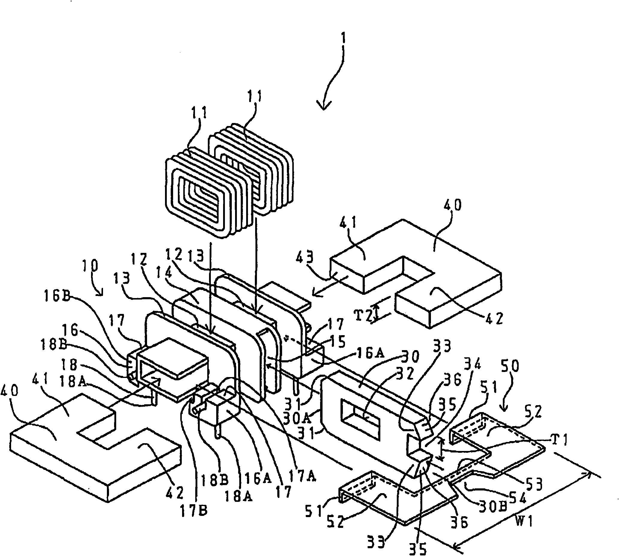
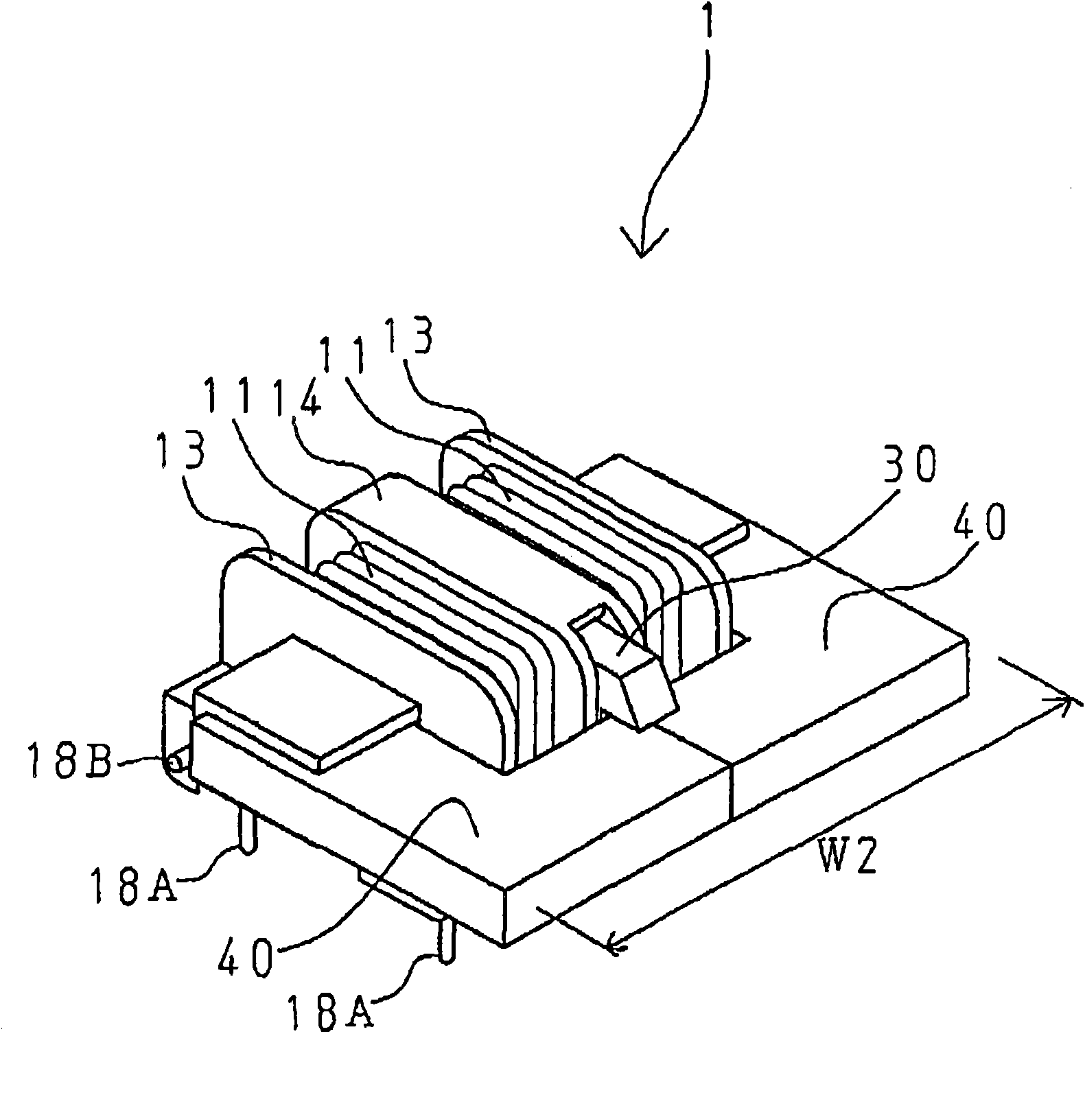
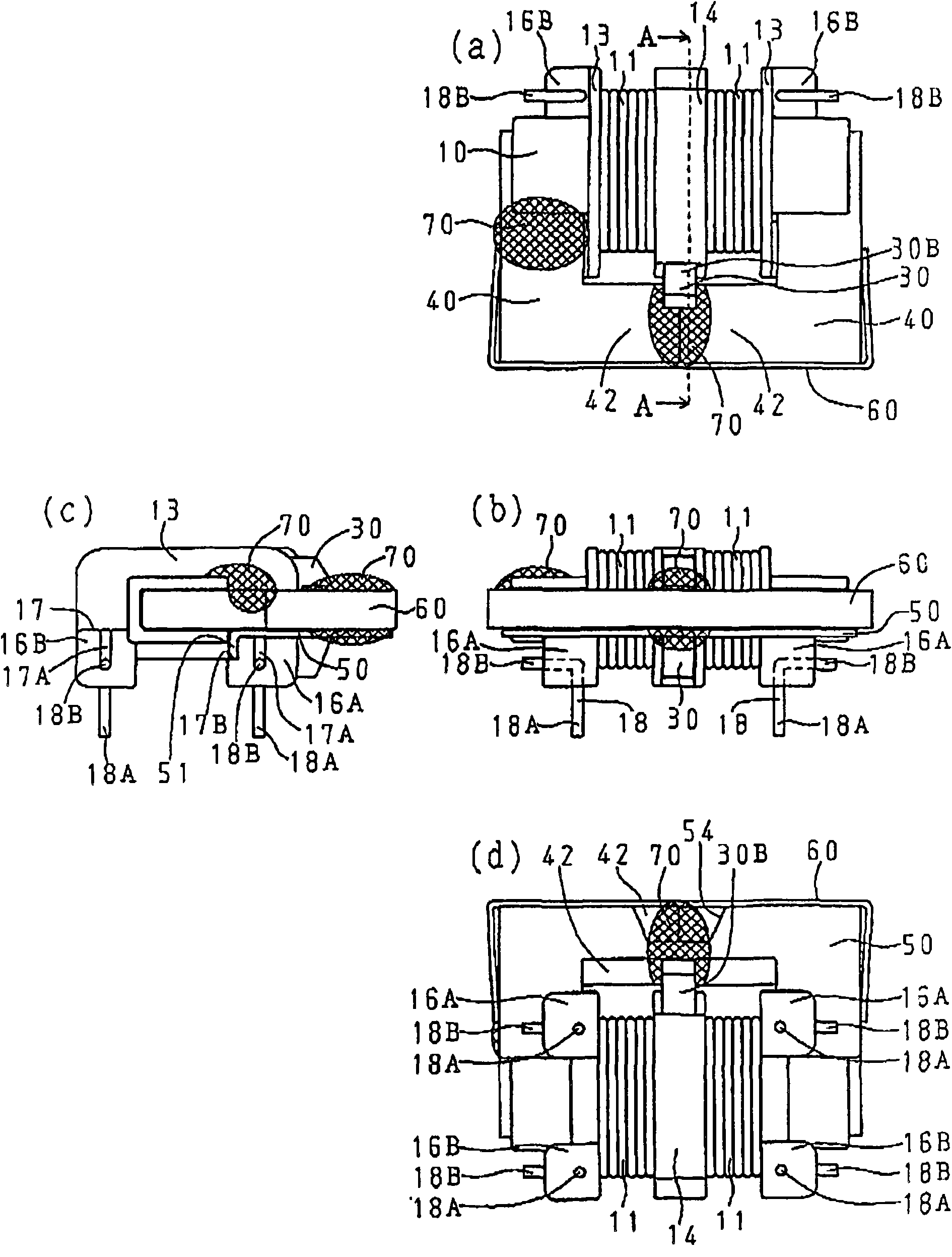
[0029] figure 1 It is an exploded perspective view of main parts of the line filter according to the first embodiment of the present invention. figure 2 yes figure 1 The main part of the line filter in the complete perspective view. image 3 It is a plan view (a), a front view (b), a side view (c), and a bottom view (d) of the completed line filter of the present invention. Figure 4 yes image 3 Sectional view of part A-A of the line filter in . Figure 5 With image 3 A flow diagram of the magnetic flux corresponding to the common-state noise in . Figure 6 With image 3 Flow plot of magnetic flux corresponding to normal noise in .

[0030] exist Figure 1 to Figure 6 Among them, the line filter 1 of this embodiment includes: a terminal bobbin 10 , a common mode core 40 , a normal mode core 30 , a bracket 60 , and a cover 50 .

[0031] The terminal-equipped bobbin 10 is composed of an integral molded product of synthetic resin, and includes: a winding core 12 aro...

no. 2 approach

[0061] Figure 7 It is an exploded perspective view of the line filter 1 according to the second embodiment of the present invention. exist Figure 7 In , the same reference numerals are assigned to the same components as those of the first embodiment, and repeated explanations will be omitted.

[0062] In the second embodiment, the difference from the first embodiment is that although the support portion 53 of the cover 50 is pressed against the front end 37 of the inclined surface 36 of the magnetic leg bottom surface 35 of the substantially A-shaped normal mode magnetic core 30, the A flat surface 44 is provided on the bottom surface 35 of the magnetic foot to which the support portion 53 of the cover 50 is pressed.

[0063] In this way, the above-mentioned effects can be obtained, and the support portion 53 of the cover 50 can face-contact and press-contact the flat surface 44 of the magnetic foot bottom surface 35 and the positioning of the normal mold core 30 can be re...


PUM


Abstract

A line filter of the invention is to sufficiently ensure an insulation distance between an L-shaped terminal and a common mode magnetic core equipped on a terminal platform, and furthermore position a normal mode magnetic core which is inserted from a side surface of a winding tube. The line filter is provided with the following components: a terminal-equipped winding tube (10) which comprises a core winding part (12) coiled by a pair of coils, two end flanges (13) provided at two ends of the core winding part (12), the terminal platform (16) provided below the two end flanges, and an L-shaped terminal (18) provided below the terminal platform; a transversely equipped common mode magnetic core (40) which inserts one magnetic pin (41) into the core winding part and form a closed magnetic path; the common mode magnetic core (30) which is magnetically coupled with the closed magnetic path of the common mode magnetic core and is inserted into a recess (15) that is provided at a side surface of a middle flange (14); and an insulative cover (50) which is provided between the common mode magnetic core and the terminal and is blocked with the terminal-equipped winding tube (10) when the normal mode magnetic core which is inserted into the recess is jointed through pressure joint.

Description

technical field [0001] This invention relates to line filters used in various electronic devices. Background technique [0002] Such as Figure 8 As shown, the conventional line filter consists of a bobbin 102 wound with a pair of coils 101, a vertical U-shaped common mode core 103 with a magnetic foot inserted in the bobbin 102, and a H Formed normal mode core 104, terminals 105 protruding from the terminal block of bobbin 102 to the board mounting surface, and brackets 106 sandwiching common mode core 103 can remove common mode noise and normal noise (for example, patent document 1). [0003] Patent Document 1: Japanese Patent Application Laid-Open No. 9-139317 [0004] Figure 8 The common mode core and the normal mode core are arranged on the bobbin in the longitudinal direction of the line filter, thereby increasing the height, and because the coil end is wound on the terminal protruding from the terminal block of the bobbin to the board mounting surface Therefore, t...

Claims


Application Information

Patent Timeline
Patent Type & Authority Applications(China)
IPC IPC(8): H01F17/04H01F27/26H01F27/02
CPCH01F17/06H01F17/062H01F27/24H01F27/29H01F27/32H01F41/06
Inventor 成田敏洋
Owner TOKYO PARTS IND CO LTD
Why Eureka
Try Eureka