Method for automatically compensating ascending optical loss gain and near end of optical fiber repeater

A technology of optical fiber repeater and gain compensation, which is applied in the field of mobile communication, can solve problems such as complex algorithms, low reliability, and complex software design, and achieve the effects of simple and effective algorithms, high reliability, and simple software design and debugging

Active Publication Date: 2011-05-04
深圳市虹远通信有限责任公司
View PDF3 Cites 10 Cited by
  • Summary
  • Abstract
  • Description
  • Claims
  • Application Information

AI Technical Summary

Problems solved by technology

Calculation based on RF power collection, non-direct compensation of optical loss gain, the near-far end gain allocation and noise issues must be considered The algorithm is complex, depends on the communication interaction between the near and far ends, low reliability and complex software design

Method used


Image

  • Method for automatically compensating ascending optical loss gain and near end of optical fiber repeater
  • Method for automatically compensating ascending optical loss gain and near end of optical fiber repeater
  • Method for automatically compensating ascending optical loss gain and near end of optical fiber repeater

Examples


Embodiment Construction

[0032] In order to make the object, technical solution and advantages of the present invention clearer, the present invention will be further described in detail below in conjunction with the accompanying drawings and embodiments. It should be understood that the specific embodiments described here are only used to explain the present invention, not to limit the present invention.

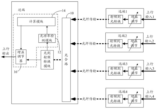
[0033] figure 1 The uplink of the optical fiber repeater provided by the embodiment of the present invention is shown, and other components irrelevant to the present invention are omitted for the convenience of explaining the problem.

[0034] The number of remote ends carried by the near end of the optical fiber repeater is determined by the actual project. The embodiment of the present invention is a typical 1 to 4. After the uplink input of the 4 remote ends is adjusted by gain, the radio frequency signal is converted into an optical signal. Optical fiber transmission to the proximal end. The ...


PUM


Abstract

The invention is suitable for the field of mobile communication, and provides a method for automatically compensating the ascending optical loss gain of an optical fiber repeater and the near end of the optical fiber repeater. The method provided by the invention comprises the following steps: combining optical signals transmitted through optical fibers at the multi-path far end by utilizing an optical combiner at the near end; detecting the optical power of the optical signals output by the optical combiner to obtain the optical power value actually accepted; calculating the optical loss value required to be compensated according to the optical power value actually accepted, the combination number of the optical combiner and the preset lossless value, and outputting the corresponding radio frequency gain compensation value; and compensating by a gain regulator at the near end according to the radio frequency gain compensation value. By utilizing the superposition and loss characteristics of the optical combiner on each path of far-end optical power, the embodiment of the invention directly realizes the automatic compensation at the near end, solves the noise problem and does not need to consider the complicated gain allocation at the near end and the far end.

Description

technical field [0001] The invention belongs to the field of mobile communication, and in particular relates to a method for automatically compensating uplink optical loss gain of an optical fiber repeater and a near end of the optical fiber repeater. Background technique [0002] The optical fiber repeater consists of a near-end and one or more far-ends, and the middle is connected by an optical fiber. Due to factors such as optical fiber splitting and combining, optical fiber length, and optical fiber connectors, etc., optical path loss will occur, and the RF gain of the whole machine will also be lost due to this, so gain adjustment is required to compensate. Noise is not involved in downlink gain adjustment. Whether it is manual or automatic, the practice in the industry is basically the same, that is, it is enough to adjust the gain of each remote end separately. [0003] However, the uplink gain adjustment becomes more complicated due to the noise index problem. Curre...

Claims


Application Information

Patent Timeline
Patent Type & Authority Applications(China)
IPC IPC(8): H04B10/12H04B10/16H04B10/08H04B10/079H04B10/291
Inventor 林巍
Owner 深圳市虹远通信有限责任公司
Why Eureka
Try Eureka