Method and device for transmitting time information
A time information and time technology, applied in synchronization devices, transmission systems, digital transmission systems, etc., can solve the problems of occupying OTN overhead, unable to complete the mapping of time data, limited bytes, etc., to ensure services, easy to deploy and The effect of upgrading equipment
- Summary
- Abstract
- Description
- Claims
- Application Information
AI Technical Summary
Problems solved by technology
Method used
Image
Examples
Embodiment 1
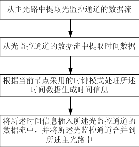
[0054] This embodiment mainly describes reading the synchronized time from the main optical path sent by the superior node, and putting the time into the downlink optical path of the current node. Such as figure 2 shown, including the following steps:
[0055] Extract the data stream of the optical monitoring channel from the main optical path;
[0056] Extract time data from the data stream of the optical monitoring channel;
[0057] processing the time data according to the clock mode adopted by the current node to generate time information;
[0058] inserting the time information into the data stream of the optical monitoring channel, and merging the optical monitoring channel into the main optical path.
[0059] The clock mode refers to the mode stipulated in the IEEE1588 protocol. In this embodiment, the clock mode adopted by the current node includes a boundary clock (Boundary Clock, BC for short) mode and a transparent clock (Transparent Clock, TC for short) mode. ...
Embodiment 2
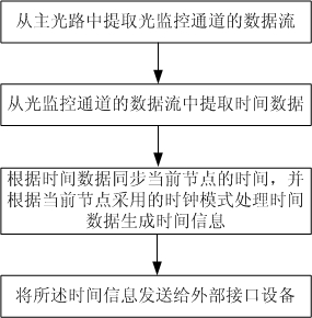
[0069] This embodiment mainly describes reading the synchronized time from the data stream of the optical monitoring channel of the main optical path, but does not put the time into the downlink optical path of the node, but provides the time to the external interface for use. Such as Figure 4 shown, including the following steps:
[0070] Extract the data stream of the optical monitoring channel from the main optical path;
[0071] Extract time data from the data stream of the optical monitoring channel;
[0072] synchronizing the time of the current node according to the time data, and processing the time data according to the clock mode adopted by the current node to generate time information;
[0073] Send the time information to the external interface device.
[0074] In this embodiment, the external interface device is a time application unit, that is, a unit that uses synchronized time, such as a 3G base station. The clock mode of the current node is determined acc...
Embodiment 3
[0081] This embodiment mainly describes reading synchronized time data from an external interface, and putting the time into the downlink optical path of the current node. Such as Figure 6 shown, including the following steps:
[0082] Extract the data stream of the optical monitoring channel from the main optical path;
[0083] Acquiring time data from an external interface device, synchronizing the time of the current node according to the time data, processing the time data according to the clock mode adopted by the current node to generate time information;
[0084] inserting the time information into the data stream of the optical monitoring channel, and merging the optical monitoring channel into the main optical path.
[0085] In this embodiment, the time on the external interface device is the synchronized absolute time. The external interface device may be an external time source unit such as a time server, or a time application unit such as a 3G base station.
...
PUM
 Abstract
Description
Claims
Application Information
 - R&D
- Intellectual Property
- Life Sciences
- Materials
- Tech Scout
- Unparalleled Data Quality
- Higher Quality Content
- 60% Fewer Hallucinations
Browse by: Latest US Patents, China's latest patents, Technical Efficacy Thesaurus, Application Domain, Technology Topic, Popular Technical Reports.
© 2025 PatSnap. All rights reserved.Legal|Privacy policy|Modern Slavery Act Transparency Statement|Sitemap|About US| Contact US: help@patsnap.com


