

Implementation method and device of point-to-multipoint pseudowire protective network
An implementation method and network technology, applied in the field of communication, to achieve the effect of improving stability and security
- Summary
- Abstract
- Description
- Claims
- Application Information
AI Technical Summary
Problems solved by technology
Method used
Image

Examples
example 1
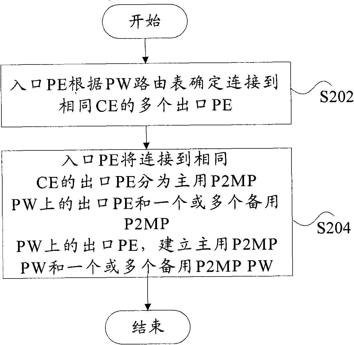
[0089] The ingress PE determines the egress PEs connected to the same CE, divides these PEs into the egress PE on the active P2MP PW and the egress PE on the standby P2MP PW, and establishes the active P2MP PW and the standby P2MP PW according to the above grouping.
[0090] Image 6 It is a flowchart of the method for implementing the egress PE protection of P2MP PW in Example 1 of the embodiment of the present invention, such as Image 6 As shown, the method includes the following steps S601 to S607:
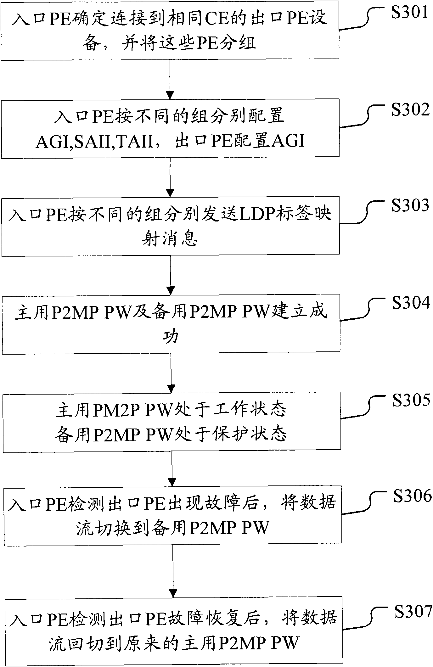
[0091] Step S601, the ingress PE is configured with AII; the egress PE connected to the same CE is configured with the same AII.
[0092] for Figure 4 In the protection network shown, PE1 is the ingress PE, the operator's edge devices PE2, PE3, PE4, and PE5 are the egress PEs, AII11 is configured on PE1, AII21 is configured on PE4 and PE2, and AII31 is configured on PE3 and PE5.
[0093] In step S602, the AII information is announced through BGP, OSPF and other protocols.
[0094] for ...
example 2
[0107] After the active and standby P2MP PWs are established, when the active P2MP PW fails, the data stream is switched to the standby P2MP PW.
[0108] Figure 7 It is a flow chart of the method for implementing P2MP PW export PE protection in Example 2 of the embodiment of the present invention, such as Figure 7 As shown, the method includes the following steps S701 to S702:
[0109] In step S701, the ingress PE detects that the egress PE of the primary P2MP PW has a failure.
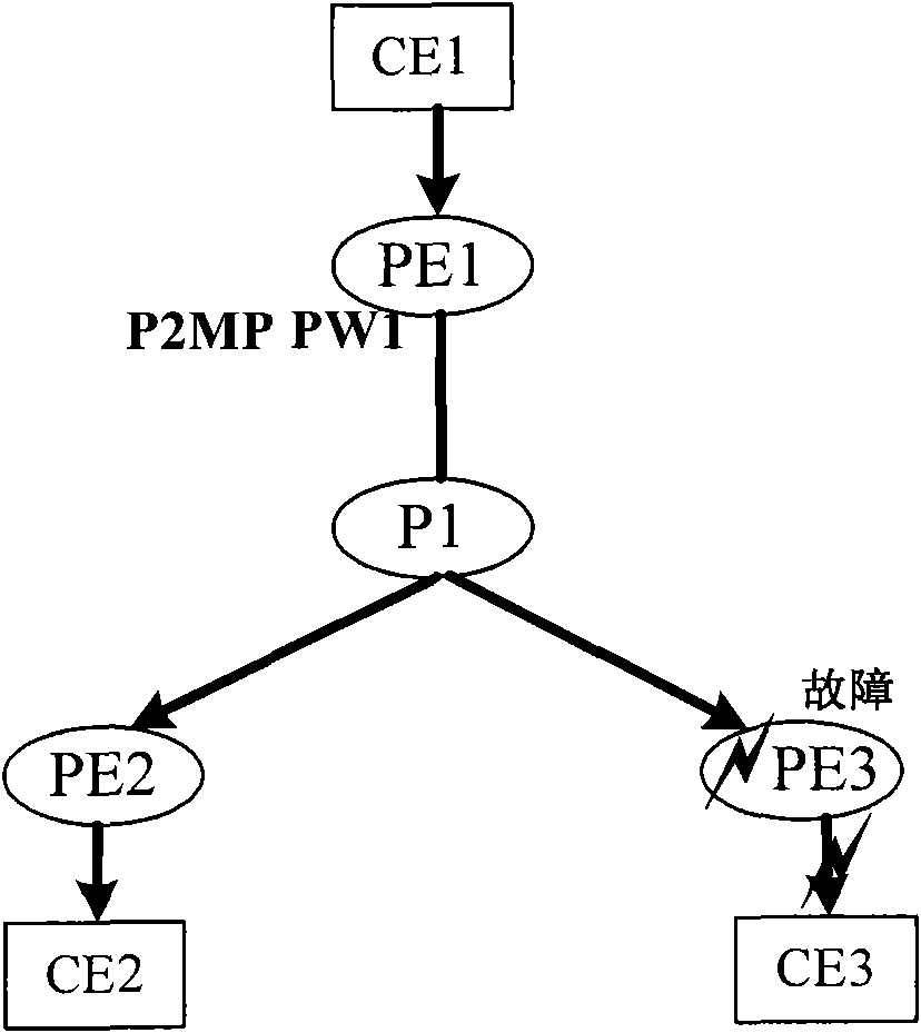
[0110] Figure 5 It is a schematic diagram of the failure of the main P2MP PW egress PE according to the embodiment of the present invention. Figure 5 In the protection network shown, PE1 can detect that PE2 or PE3 is faulty through P2MP BFD.
[0111] In step S702, the data stream is switched to the backup P2MP PW, and the primary P2MP PW no longer forwards the data stream.
[0112] for Figure 5 In the protection network shown, when PE1 detects a failure in either PE2 or PE3, it will switch the data stream ...
example 3
[0114] When the main P2MP PW fails and recovers, the data stream is switched to the original main P2MPPW.
[0115] Figure 8 It is a flowchart of the method for implementing the egress PE protection of P2MP PW in Example 3 of the embodiment of the present invention, such as Figure 8 As shown, the method includes the following steps S801 to S802:
[0116] In step S801, the ingress PE detects that the egress PE of the primary P2MP PW fails to recover.
[0117] E.g, Figure 4 The shown P2MP PW egress PE protection network can also be seen as a schematic diagram after the main P2MP PW egress PE failure is restored. PE1 can detect the fault recovery of PE2 and PE3 through P2MP BFD.
[0118] In step S802, the data flow is switched back to the original primary P2MP PW, and the backup P2MP PW no longer forwards the data flow.
[0119] E.g, Figure 4 The shown P2MP PW egress PE protection network can also be seen as a schematic diagram after the main P2MP PW egress PE failure is restored. Aft...
PUM
 Abstract
Description
Claims
Application Information