
Protective circuit, protective surface and electronic system

A technology for protecting circuits and electronic systems, applied in the direction of printed circuits, printed circuits, circuit devices, etc.

Inactive Publication Date: 2014-02-19
LUCAS AUTOMOTIVE GMBH
View PDF4 Cites 0 Cited by
  • Summary
  • Abstract
  • Description
  • Claims
  • Application Information

AI Technical Summary

Problems solved by technology

[0010]However, if multiple short circuits occur in parallel, the protection devices described here cannot provide adequate protection

Method used


Image

  • Protective circuit, protective surface and electronic system
  • Protective circuit, protective surface and electronic system
  • Protective circuit, protective surface and electronic system

Examples


Embodiment Construction

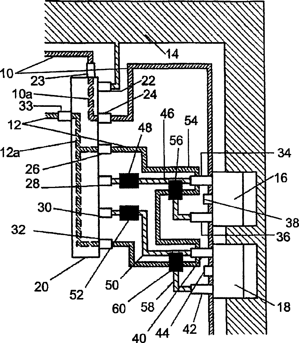
[0080] A part of the supply voltage trace 14 , two transistors 16 , 18 and a driver module 20 are also arranged on this part of the printed circuit board.

[0081] The eight terminals of the drive module 20 relate to the embodiment described below; the eight terminals are the supply voltage terminal 22, the two conductor loop terminals 23, 24 of the first conductor loop 10, the three conductor loop terminals of the second conductor loop 12 Ground terminals 26, 32, 33 and two connection terminals 28, 30 with supply voltage potential.

[0082] The supply voltage terminal 22 is electrically connected to the supply voltage trace 14 .

[0083] The first conductor loop 10 is connected to the drive module 20 via a conductor loop terminal 23 . In the drive module 20 , a part 10 a of the first conductor loop 10 forms a connection between a conductor loop terminal 23 and a conductor loop terminal 24 . The first conductor loop 10 leaves the drive module 20 via a conductor loop connecti...


PUM


Abstract

A protective circuit arranged on a Printed Circuit Board (PCB) has two conductor loops. At least one supply voltage track, at least one semiconductor switch and at least one control component are arranged on the PCB. A first terminal of the control component and a first terminal of the semiconductor switch are connected electrically. A first conductor loop of the protective circuit is arranged on the PCB so that it surrounds an electrically conducting connection between the supply voltage track and the semiconductor switch and / or the control component. A second conductor loop is arranged on the PCB so that it surrounds the electrically conducting connection between the first terminal of the control component and the first terminal of the semiconductor switch, and thereby screens the same from the semiconductor switch and at least from those regions of the control component that are also connected to the supply voltage track.

Description

technical field [0001] The invention relates to a protective circuit arranged on a printed circuit board, a protective surface arranged between two printed circuit boards and an electronic system for operating an electromechanical parking brake system of a vehicle. Background technique [0002] The following describes protective devices for protecting safety-related electronic circuits against failure. The device is based on the self-monitoring principle and facilitates continuous monitoring of important operating parameters, such as voltages in electronic circuits, thus enabling early detection of impending failures. [0003] The severe effects of such short circuits are prevented by using protective elements for early detection of short circuits between traces on the printed circuit board, which are applied directly to the printed circuit board. [0004] Short circuits caused, for example, by moisture penetrating the circuit housing, leading to unintentional activation of...

Claims


Application Information

Patent Timeline
Patent Type & Authority Patents(China)
IPC IPC(8): B60T13/74G01R31/02H05K1/16
CPCB60T13/746G01R31/2818H05K2201/10053H05K1/0268G01R31/025H05K2201/09781H05K1/0265H05K2201/10166G01R31/52
Inventor 马蒂亚斯·富克斯马尔科·荣格拉斯卢茨·穆德斯贝内迪克特·奥利格
Owner LUCAS AUTOMOTIVE GMBH
Learn More