Self-positioning fixture

A self-positioning and fixture technology, applied in positioning devices, clamping, manufacturing tools, etc., can solve the problems of reducing processing efficiency, time-consuming, processing deviation, etc., and achieve the effect of improving precision and processing efficiency

Inactive Publication Date: 2011-05-11
汪焱
View PDF0 Cites 5 Cited by
  • Summary
  • Abstract
  • Description
  • Claims
  • Application Information

AI Technical Summary

Problems solved by technology

It is often encountered in factories that L-shaped or strip-shaped workpieces need to be clamped on the side for punching or other processing. Although the existing fixtures have the clamping function, they often need to be positioned before they can be processed. Because the fixture does not have Self-positioning function, so there is often a large deviation after processing
At the same time, in the positioning process, it takes time, thus greatly reducing the processing efficiency

Method used


Image

  • Self-positioning fixture
  • Self-positioning fixture

Examples


Embodiment Construction

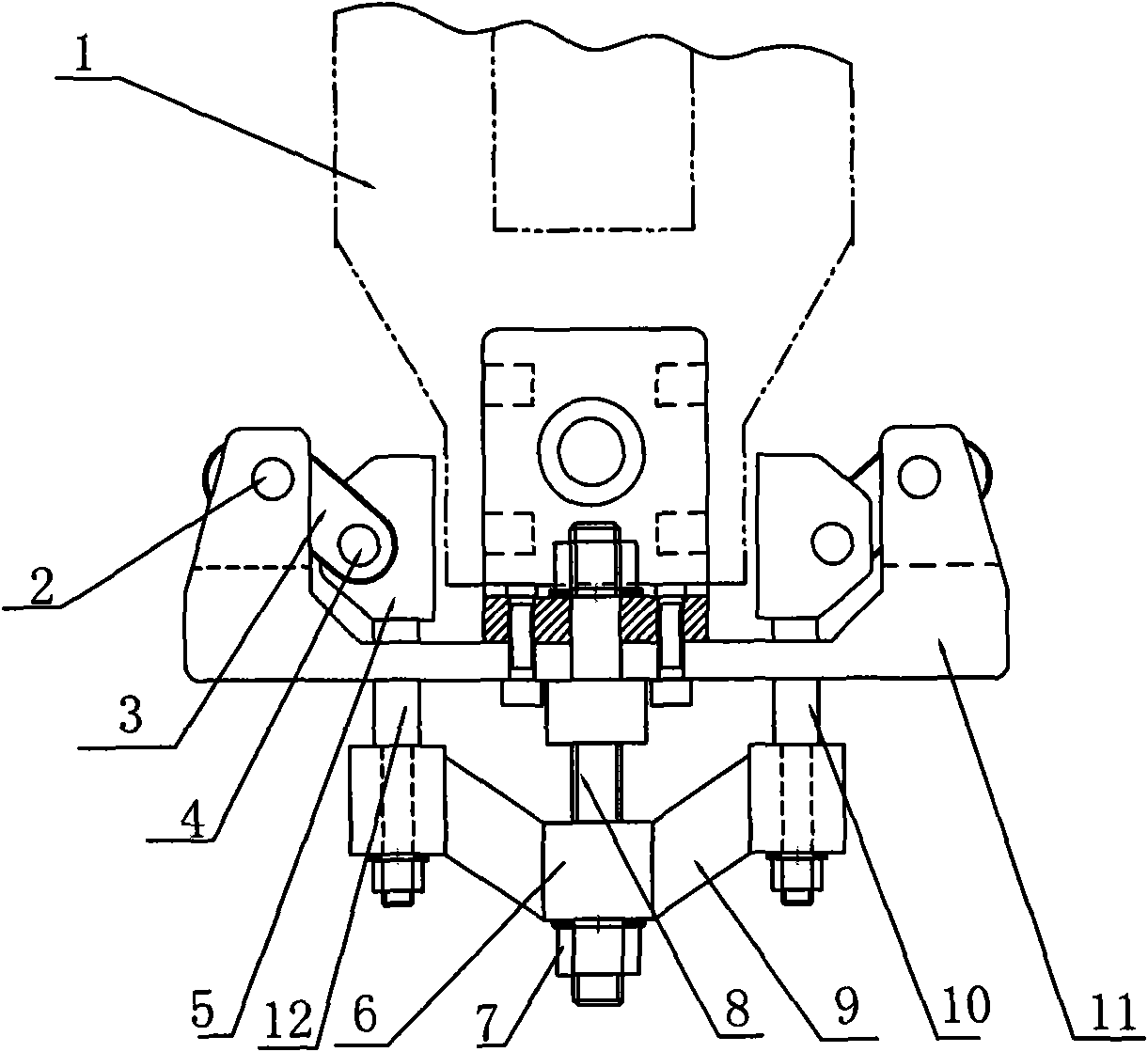
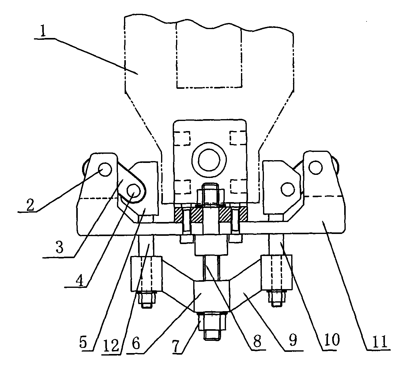
[0009] A self-positioning fixture of the present invention, such as figure 1 As shown, it includes a U-shaped mount body 11, a lifting device and a clamping device.

[0010] The lifting device includes a screw rod 8, a nut 7 adapted to the screw rod 8 and connected to the screw rod 8, a left push rod 12, a right push rod 10 and a push rod seat. The rod seat is symmetrically connected with two horizontal bars 9 on both sides of the bushing 6, the bushing 6 is set on the screw 8, and the nut 7 is connected to the screw at the bottom of the bushing 6; hole, two push rods are located in the through hole, and can slide up and down, left and right along the through hole, and two cross bars 9 are connected with the lower ends of the two push rods respectively, so that the rise of the push rod seat drives the rise of the two push rods.

[0011] The clamping device includes two clamping blocks 5 and two rotating levers 3, and the two clamping blocks 5 are fixedly connected to the uppe...


PUM


Abstract

The invention relates to a self-positioning fixture. The self-positioning fixture comprises a U-shaped seat frame body [11], a lifting device and a clamping device, wherein the lifting device comprises a screw [8], a nut [7], two carrier rods and a carrier rod seat; one end of the screw [8] is fixedly connected to the middle of the seat frame body [11]; on the carrier rod seat, two transverse rods [9] are fixedly connected to the two side faces of a shaft sleeve [6] symmetrically; the shaft sleeve [6] is sleeved on the screw [8]; a through hole is formed on the two sides of the seat frame body [11] respectively; the two carrier rods are positioned in the through holes; the two transverse rods [9] are connected with the lower ends of the two carrier rods respectively; the clamping device comprises two clamping blocks [5] and two rotating levers [3]; the two clamping blocks [5] are fixedly connected to the upper ends of the two carrier rods respectively; and each clamping block is hinged with one end of each rotating lever [3], and the other end of each rotating lever [3] is hinged with the upper parts of the two sides of the seat frame body [11]. The self-positioning fixture can clamp and position workpieces, so machining accuracy and machining efficiency are greatly improved.

Description

technical field [0001] The invention relates to a clamp, in particular to a pair of self-positioning clamps. Background technique [0002] Fixtures are widely used in factories. The function of the fixture is to fix the workpiece to be processed and then machine it. The shape of the workpiece is various, so the structure of the fixture is also various. It is often encountered in factories that L-shaped or strip-shaped workpieces need to be clamped on the side for punching or other processing. Although the existing fixtures have the clamping function, they often need to be positioned before they can be processed. Because the fixture does not have Self-positioning function, so there is often a large deviation after processing. At the same time, it takes time during the positioning process, thus greatly reducing the processing efficiency. Contents of the invention [0003] The purpose of the present invention is to provide a self-positioning fixture to improve machining a...

Claims


Application Information

Patent Timeline
Patent Type & Authority Applications(China)
IPC IPC(8): B23Q3/00
Inventor 余磊汪焱
Owner 汪焱
Why Eureka
Try Eureka