

Industrial gas burner
An industrial gas and burner technology, which is applied in the direction of gas fuel burners, burners, combustion methods, etc., can solve the problems of complicated structure, poor flame stability, high pressure and cleanliness requirements, so as to avoid clogging and deposition, and overcome backlash fire effect
- Summary
- Abstract
- Description
- Claims
- Application Information
AI Technical Summary
Problems solved by technology
Method used
Image

Examples
Embodiment Construction
[0024] specific implementation plan
[0025] Accompanying drawing is embodiment of the present invention.
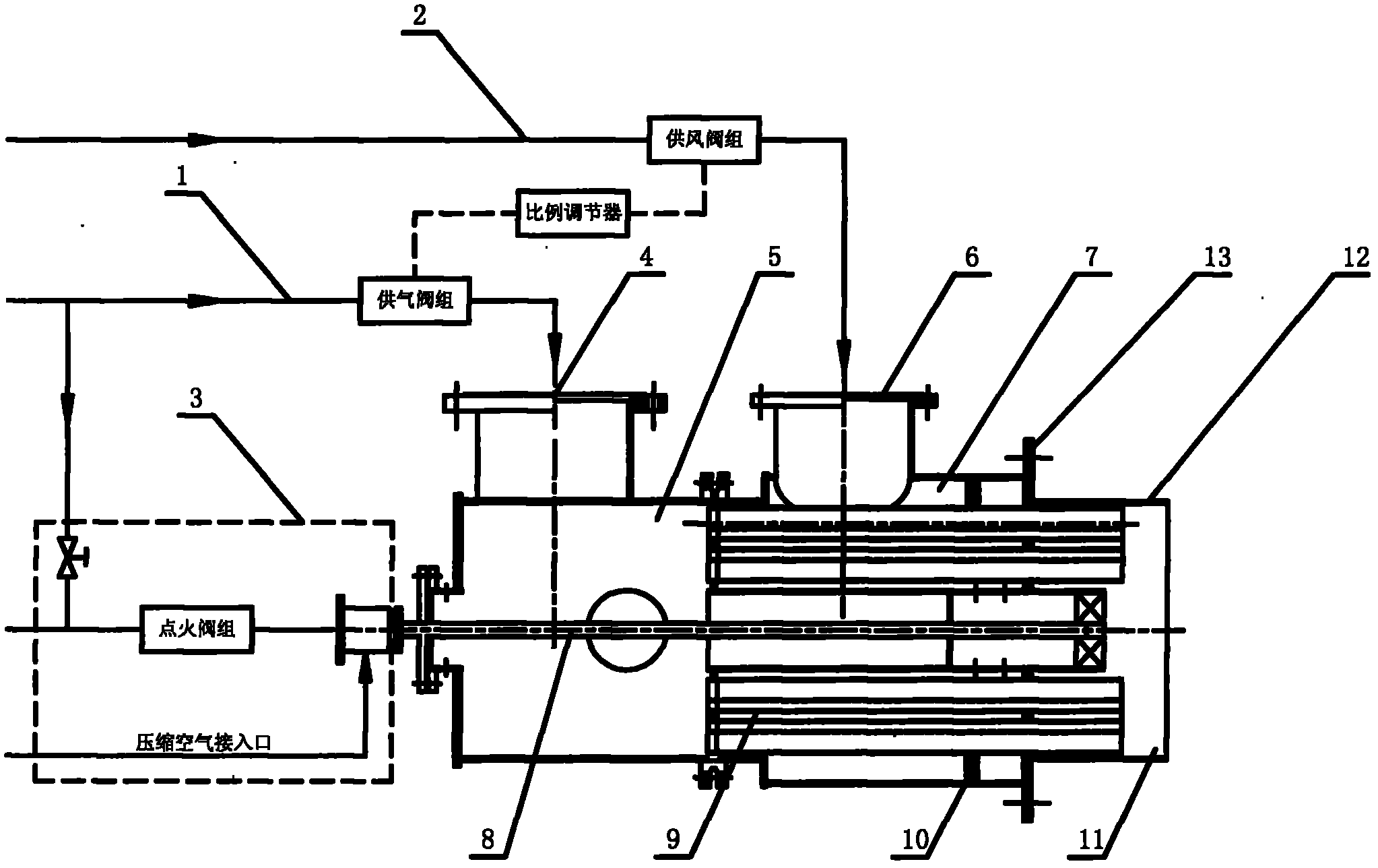
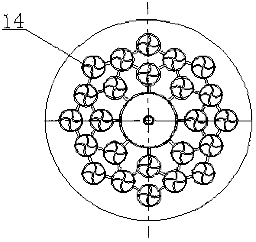
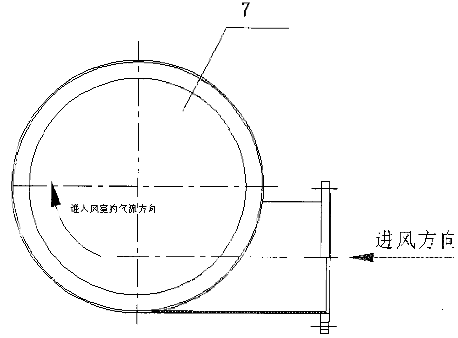
[0026] attached figure 1 The medium fuel gas enters the gas chamber 5 from the gas supply pipeline 1 through the air inlet 4 . The gas chamber 5 is separated from the air chamber 7 with a dividing plate. A gas distribution tube bundle 9 is arranged on the partition, and the gas distribution tube bundle 9 reaches the air-mixing combustion zone 11 for mixed combustion with the combustion-supporting air. In this embodiment, 24 gas distribution pipes have been used (see attached figure 2 ), each gas distribution pipe is provided with holes communicating with the combustion air chamber 7 (these holes are not shown in the figure). The diameter of the hole is Φ14mm. The length of the guide vane is 50-90 mm, the lead of the guide vane is 1, the diameter of each gas distribution pipe is 45 mm, and the length is 900 mm. The combustion-supporting air enters the combustion-sup...
PUM
 Abstract
Description
Claims
Application Information