Method and structure for molding leadframe strip

A lead frame strip and lead frame technology is applied in the fields of semiconductor devices, semiconductor/solid-state device manufacturing, semiconductor/solid-state device components, etc., and can solve the problems of difficult output per unit time, waste of lead frame strip 1 space, etc.

Active Publication Date: 2013-03-27
日荣半导体(上海)有限公司
View PDF4 Cites 0 Cited by
  • Summary
  • Abstract
  • Description
  • Claims
  • Application Information

AI Technical Summary

Problems solved by technology

However, the 1:1 arrangement ratio design of the flow channel support 12 and the lead frame unit 13 has too many flow channel support 12, which relatively limits the space that the lead frame bar 1 can be used to set the lead frame unit 13. Space, that is to say relatively limit the total number of units of the lead frame unit 13
As a result, only a limited amount of the encapsulant 173 can be formed on the lead frame bar 1 every time the sealing process is performed, and a lot of space in the lead frame bar 1 must be wasted as the runner support 12 , thus making it difficult to further increase the output per unit time (units per hour, UPH) of the sealing procedure

Method used


Image

  • Method and structure for molding leadframe strip
  • Method and structure for molding leadframe strip
  • Method and structure for molding leadframe strip

Examples


Embodiment Construction

[0031] In order to make the above objects, features and advantages of the present invention more comprehensible, preferred embodiments of the present invention are exemplified below and described in detail in conjunction with the accompanying drawings. Furthermore, the directional terms mentioned in the present invention, such as "up", "down", "front", "back", "left", "right", "inside", "outside" or "side", etc., It is only for orientation with reference to the attached drawings. Therefore, the directional terms used are used to illustrate and understand the present invention, but not to limit the present invention.

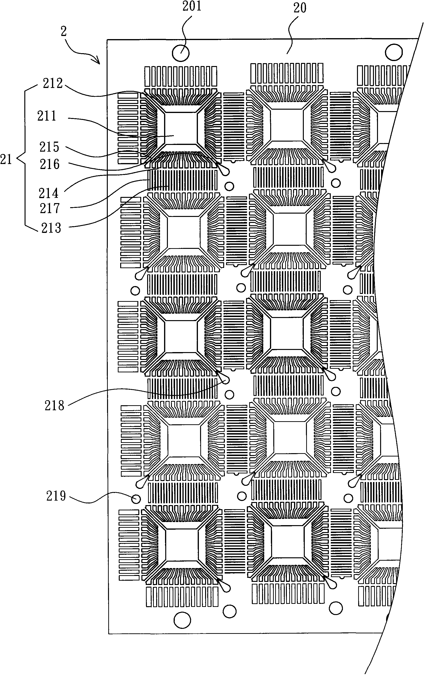
[0032] Please refer to image 3 and 4 As shown, the sealing method and sealing structure of lead frame strips according to the first embodiment of the present invention are mainly used in the manufacture of semiconductor packaging products with four rows of lead frames, for example, in the manufacture of quad flat packages (quad flat packages, QFP), square fla...


PUM


Abstract

The invention discloses a method and structure for molding a leadframe strip, and the method mainly comprises the following steps: providing a leadframe strip, wherein the leadframe strip is provided with a plurality of leadframe units; and utilizing an arc-shaped connecting gate to connect a molding compound is connected between two corners of two adjacent leadframe units, wherein the arched connecting gate does not occupy the space, which is used for the installation of the leadframe units, of the leadframe strip, thus the installation of the existing flow channel bracket can be omitted for the integral leadframe strip, namely outer leads of the two adjacent leadframes can also be arranged in a staggered mode at the same staggered arrangement region. Therefore, the method and structure for molding the leadframe strip are favorable for promoting the space utilization ratio of the leadframe strip, increasing the layout quantity of the leadframe units, and increasing the units per hour of the molding procedure, and relatively reducing the average molding cost of a semiconductor packaging structure.

Description

【Technical field】 [0001] The present invention relates to a sealing method and sealing structure for lead frame strips, in particular to a method that can increase the output per unit time (units per hour, UPH) and relatively reduce the problem of mold flow punching. The sealing method and sealing structure of QFP lead frame strips. 【Background technique】 [0002] Nowadays, in order to meet various packaging requirements, the semiconductor packaging industry has gradually developed various types of packaging structures. Among them, silicon chips (chips) cut from semiconductor silicon wafers (wafers) are usually firstly processed by wire bonding. ) or bumping (bumping) and other appropriate methods to select and fix on the leadframe (leadframe) or substrate (substrate), and then use the encapsulation gel to encapsulate and protect the silicon chip, so that the basic structure of a semiconductor package structure can be completed. Common package structures with lead frames in...

Claims


Application Information

Patent Timeline
Patent Type & Authority Patents(China)
IPC IPC(8): H01L21/56H01L23/495H01L23/31
CPCH01L24/97H01L2224/48247H01L2224/49171H01L2924/181
Inventor 周素芬
Owner 日荣半导体(上海)有限公司
Why Eureka
Try Eureka