Cable connector component and manufacturing method thereof

A technology for cable connectors and manufacturing methods, which is applied to parts of connecting devices, parts of lines/collectors, connections, etc., which can solve the problem of increasing connector costs, increasing welding time, and the inability to realize printed circuit boards and cables. Fast welding and other issues, to save welding time, reduce costs, and shorten assembly time

Inactive Publication Date: 2011-05-11
FOXCONN (KUNSHAN) COMPUTER CONNECTOR CO LTD +1
View PDF3 Cites 16 Cited by
  • Summary
  • Abstract
  • Description
  • Claims
  • Application Information

AI Technical Summary

Problems solved by technology

[0003] However, since the upper and lower surfaces of the rear end of the printed circuit board 30 are to be welded with the wire 41 in the cable 40, it is necessary to wait until the conductive sheet on the upper surface of the rear end of the printed circuit board 30 and the wire 41 in the cable 40 are completely welded, and then Welding the conductive sheet on the lower surface of the rear end of the printed circuit board 30 and the wire 41 in the cable 40, due to the two times of welding between the printed circuit board 30 and the cable 40, this will undoubtedly increase the welding time, and the printed circuit board cannot be realized. Fast soldering to and from cables
In addition, each connector is also provided with a pair of upper and lower clips 81, 82 mainly used for clamping and positioning the inner wire 41 of the cable 40. However, due to the existence of the above-mentioned upper and lower clips 81, 82, the entire connector is increased. the cost of

Method used


Image

  • Cable connector component and manufacturing method thereof
  • Cable connector component and manufacturing method thereof
  • Cable connector component and manufacturing method thereof

Examples


Embodiment Construction

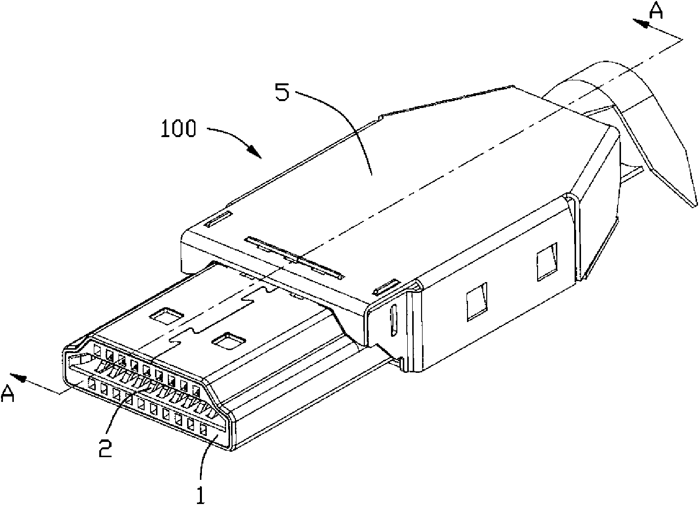
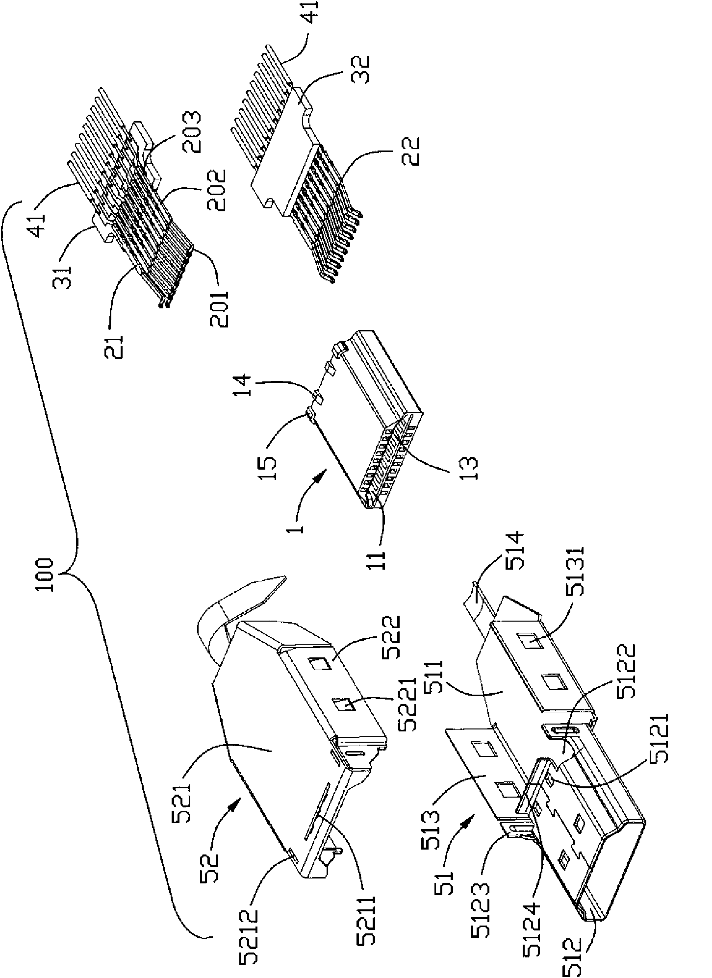
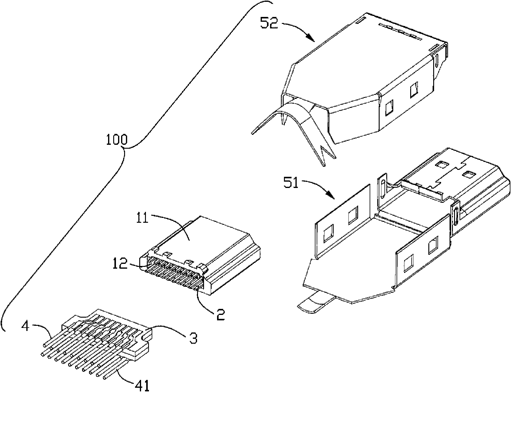
[0017] see Figure 1 to Figure 3 and Figure 5 As shown, the cable connector assembly 100 of the present invention includes an insulating body 1, a plurality of conductive terminals 2 housed in the insulating body 1, a printed circuit board 3 electrically connected to the conductive terminals 2, and a printed circuit board 3 electrically connected to the printed circuit board 3. The cable 4 and the metal shielding shell 5 covering the insulating body 1 and the printed circuit board 3 , wherein the printed circuit board 3 is composed of an upper circuit board 31 and a lower circuit board 32 .

[0018] see Figure 2 to Figure 4 The insulating body 1 has a front end face and a rear end face opposite to the front end face, a receiving chamber 11 is formed by inwardly recessing the front end face of the insulating body 1 , and a recessed cavity 12 is formed by inwardly recessing the rear end face of the insulating body 1 . Two rows of terminal receiving grooves 13 are provided on...


PUM


Abstract

A cable connector component comprises an insulating body, a plurality of conductive terminals, a printed circuit board (PCB), a cable and a metal shelter casing, wherein a concave cavity is arranged at the tail part of the insulating body; the conductive terminals are accommodated in the insulating body; the front end part of the PCB is accommodated in the concave cavity of the insulating body and electrically connected with the conductive terminals; the cable is electrically connected with the rear end part of the PCB; the insulating body and the PCB are coated by the metal shelter casing; and the PCB comprises an upper circuit board and a lower circuit board. As the electrical connection of the upper and the lower circuit boards and the cable can be finished through once welding, the cable connector component has the advantage of high assembly efficiency.

Description

【Technical field】 [0001] The invention relates to a cable connector assembly, in particular to a cable connector assembly containing a double-layer PCB board and a manufacturing method thereof. 【Background technique】 [0002] At present, the electrical connection between the conductive terminals and the cables in the cable connector assembly can be transferred through the PCB board. The Chinese Invention Patent Announcement No. CN2711949Y discloses a connector. Please refer to the drawings and the symbols in the patent No., which includes the shielding shell 10, the plastic shell 20 assembled in the shielding shell 10, the terminal 22 accommodated in the plastic shell 100, the front end and the tail of the terminal 22 are welded and the printing is contained in the plastic shell 20 The circuit board 30 and the cable 40 welded to the conductive sheets on the upper and lower surfaces of the rear end of the printed circuit board 30, wherein the front end of the wire 41 in the c...

Claims


Application Information

Patent Timeline
Patent Type & Authority Applications(China)
IPC IPC(8): H01R12/70H01R13/00H01R13/40H01R13/648H01R43/20H01R43/02
CPCH01R13/6658H01R24/62H01R13/6593H01R13/6594Y10T29/49147
Inventor 苏聘胜李小利
Owner FOXCONN (KUNSHAN) COMPUTER CONNECTOR CO LTD
Why Eureka
Try Eureka