Apparatus and method for correcting duty cycle of clock signal

一种时钟信号、内部时钟信号的技术,应用在信息存储、功率的自动控制、数字存储器信息等方向,能够解决占空比的改变没有被校正、占空比没有被校正、内部时钟信号不精确占空比等问题

Active Publication Date: 2011-05-11
SK HYNIX INC
View PDF6 Cites 30 Cited by
  • Summary
  • Abstract
  • Description
  • Claims
  • Application Information

AI Technical Summary

Problems solved by technology

However, the change in duty cycle caused by the variable delay unit 130 is not corrected for
Meanwhile, if the DCC circuit 200 is coupled to the output terminal of the DLL, a change in the duty ratio caused by the variable delay unit 130 can be corrected, but the duty ratio of the external clock EXTCLK input to the DLL is not corrected, and therefore, from The internal clock signal output by the DLL has an imprecise duty cycle

Method used


Image

  • Apparatus and method for correcting duty cycle of clock signal
  • Apparatus and method for correcting duty cycle of clock signal
  • Apparatus and method for correcting duty cycle of clock signal

Examples


Embodiment Construction

[0025] Exemplary embodiments of the present invention will be described in more detail below with reference to the accompanying drawings. However, this invention may be embodied in different forms and should not be construed as limited to the embodiments set forth herein. Rather, these embodiments are provided so that this disclosure will be thorough and complete, and will fully convey the scope of the invention to those skilled in the art. Throughout this disclosure, like reference numerals refer to like parts throughout the various figures and embodiments of the present invention.

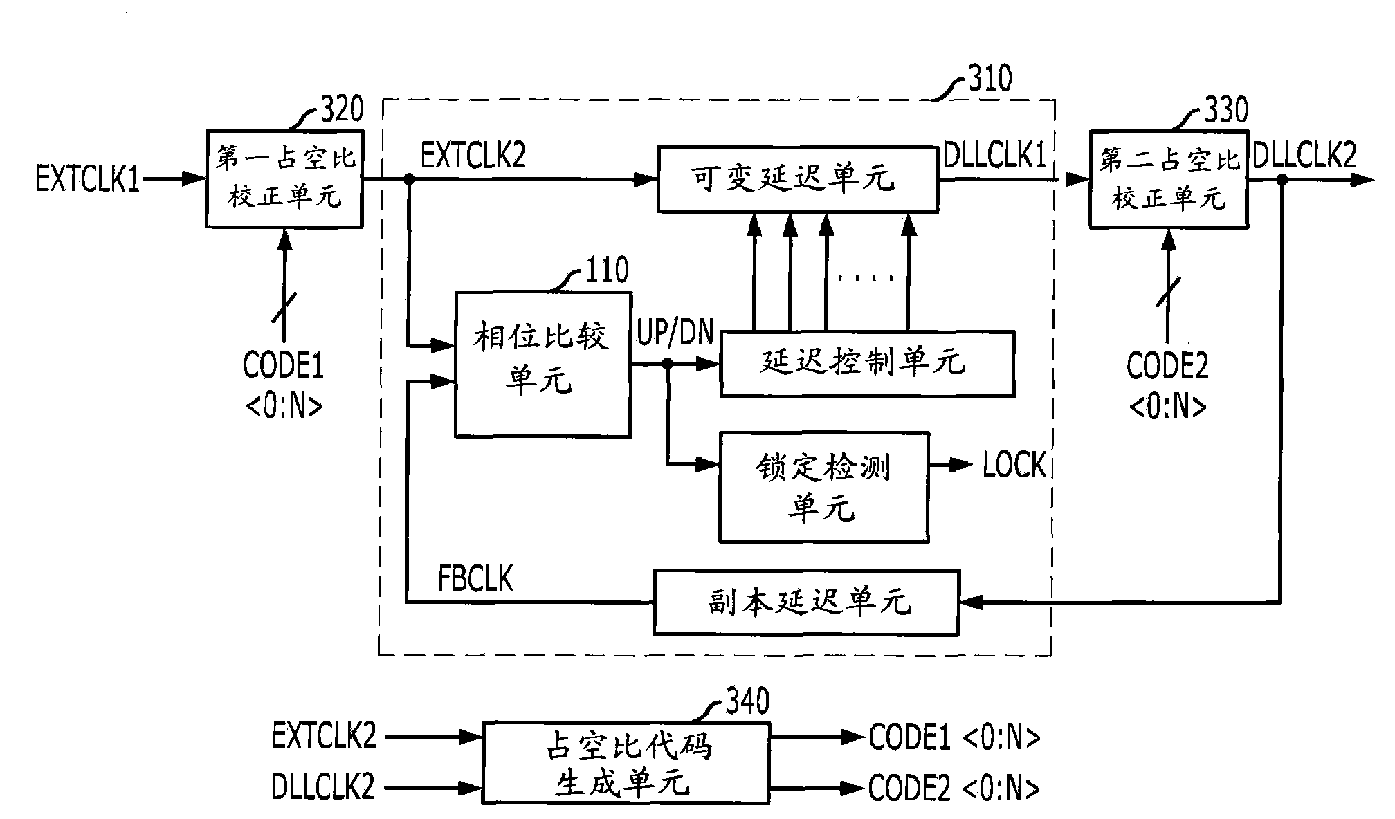
[0026] image 3 is a block diagram showing a clock correction circuit according to an embodiment of the present invention. The clock correction circuit includes a delay locked loop (DLL) 310 , first and second duty cycle correction (DCC) units 320 and 330 , and a duty code generation unit 340 . The first DCC unit 320 corrects the duty ratio of the first external clock signal EXTCLK1 in respons...


PUM


Abstract

A clock correction circuit includes a delay locked loop (DLL) configured to delay an external clock signal and to generate an internal clock signal, a first duty cycle correction (DCC) unit configured to correct a duty cycle of the external clock signal in response to a first duty cycle code, a second DCC unit configured to correct a duty cycle of the internal clock signal in response to a second duty cycle code, and a duty cycle code generation unit configured to select an output of from outputs of the first and second DCC Units and to generate the first and second duty cycle codes by detecting a duty cycle ratio of the selected output.

Description

[0001] Cross References to Related Applications [0002] This application claims priority from Korean Patent Application No. 10-2009-0104624 filed on October 30, 2009, the entire contents of which are incorporated herein by reference. Background technique [0003] Exemplary embodiments of the present invention relate to an apparatus for correcting a duty cycle of a clock signal. [0004] Clock signals are widely used in various systems and circuits to adjust the timing of operations. When clock signals are used inside systems and circuits, clock signals are often delayed. To ensure reliable operation, it is important to correct for delays. Typically a delay locked loop (DLL) is used to compensate for the delay of the clock signal. [0005] figure 1 is a block diagram showing a legacy DLL. [0006] The conventional DLL 100 includes a phase comparison unit 110 , a delay control unit 120 , a variable delay unit 130 , a replica delay unit 140 and a lock detection unit 150 . ...

Claims


Application Information

Patent Timeline
Patent Type & Authority Applications(China)
IPC IPC(8): H03K3/017H03L7/08
CPCG11C7/22G11C7/222H03K5/1565H03L7/0816G11C8/00
Inventor 沈锡辅
Owner SK HYNIX INC
Why Eureka
Try Eureka