
Channel resource allocation method, base station and relay node

A technology of relay nodes and channel resources, which is applied in channel resource allocation, base station and relay node fields, and can solve problems such as not being able to take into account pilot design

Active Publication Date: 2013-06-26
DATANG MOBILE COMM EQUIP CO LTD
View PDF4 Cites 0 Cited by
  • Summary
  • Abstract
  • Description
  • Claims
  • Application Information

AI Technical Summary

Problems solved by technology

[0010] The embodiment of the present invention provides a channel resource allocation method to solve the problem that the existing channel resource allocation method cannot take into account pilot design while improving the efficiency of RN to obtain R-PDDCH information

Method used


Image

  • Channel resource allocation method, base station and relay node
  • Channel resource allocation method, base station and relay node
  • Channel resource allocation method, base station and relay node

Examples


Embodiment Construction

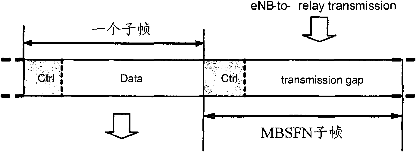
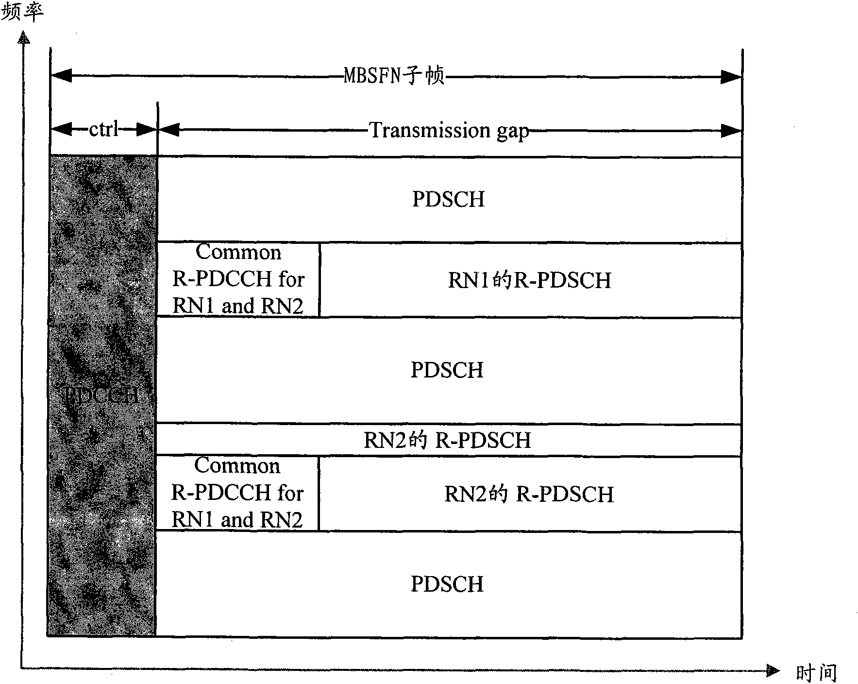
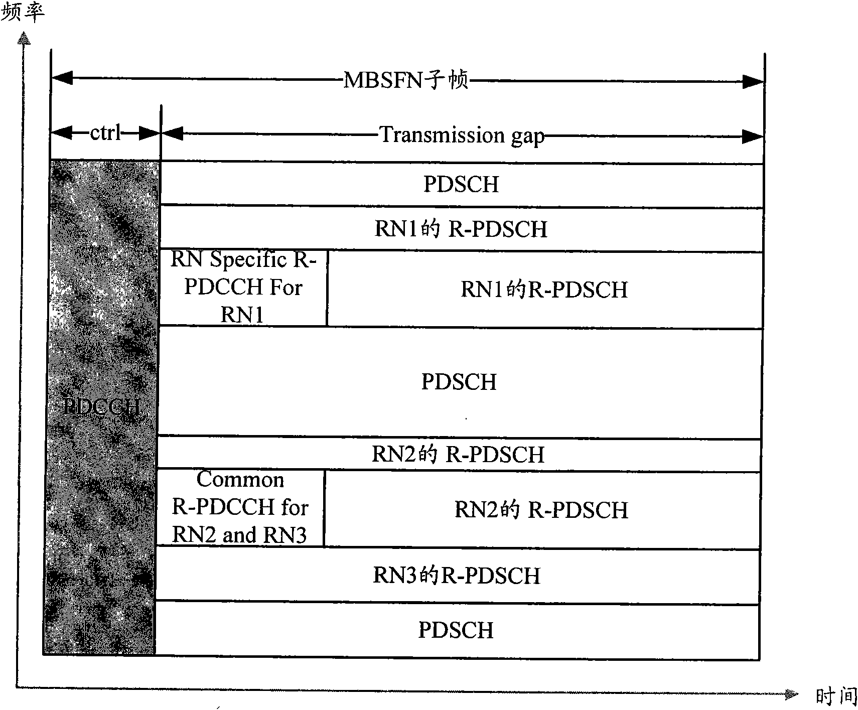
[0029] In the existing channel resource allocation method, TDM is used to transmit R-PDCCH information and R-PDSCH information in the Common R-PDCCH area. Since the Common R-PDCCH area does not have high requirements for time delay, TDM is used to transmit the information in this area. R-PDCCH information and R-PDSCH information will lead to the problem of difficult pilot design, and the RN-specific R-PDCCH area has high requirements for delay. If FDM is used to transmit R in the RN-specific R-PDCCH area - The PDCCH information and the R-PDSCH information will lead to the problem of a large delay in obtaining by the RN.

[0030] In view of the problems in the prior art, the embodiment of the present invention provides a method for allocating channel resources, so as to take into account the problem of pilot design while improving the data acquisition of RN.

[0031] Embodiments of the present invention will be described in detail below in conjunction with the accompanying draw...


PUM


Abstract

The invention discloses a channel resource allocation method, a base station and a relay node, aiming at solving the problem that the traditional channel resource distribution cannot give consideration to pilot frequency design at the same time of improving the efficiency of acquiring an R-PDDCH (Relay-Physical Downlink Control Channel) by the RN (Relay Node). The method comprises the following steps: the base station transmits R-PDCCH information and R-PDSCH (Relay-Physical Downlink Share Channel) information by adopting a TDM (Time Division Multiplexing) way in an RN-Specific R-PDCCH area in a downlink relay chain data subframe; and the base station transmits R-PDCCH information and R-PDSCH information by adopting an FDM (Frequency-Division Multiplexing) way in a Common R-PDCCH area in the data subframe. By adopting the technical scheme, the invention also simplifies the pilot frequency design at the same time of improving the efficiency of acquiring the R-PDDCH information by the RN.

Description

technical field [0001] The present invention relates to the field of wireless communication, and in particular, to a method for channel resource allocation, a base station and a relay node. Background technique [0002] In the 3GPP (3rd Generation Partnership Project, 3rd Generation Partnership Project) long-term evolution LTE-A (Long Term Evolution Advanced, long-term evolution system upgrade) system, the relay cooperative transmission method is used to improve the service quality of cell edge users. It is particularly important for the design of the control channel of the relay link to increase the wireless coverage quality of the cell. [0003] Using the relay cooperative transmission method, it is necessary to set an RN (Relay Node, relay node) in the serving cell included in the base station, and the RN provides services for the users in the serving cell. These users served by the RN are called relay users. (Subsequently denoted by R-UE). A user directly served by a b...

Claims


Application Information

Patent Timeline
Patent Type & Authority Patents(China)
IPC IPC(8): H04W72/12H04B7/26
Inventor 潘学明沈祖康肖国军孙韶辉王立波
Owner DATANG MOBILE COMM EQUIP CO LTD
Learn More