Torque limiter

A torque limiter and shear valve technology, applied in the direction of couplings, slip couplings, rigid shaft couplings, etc., can solve problems such as difficult torque limiter re-running, to achieve fast scattering, easy Scattering effect

Active Publication Date: 2011-05-11
JTEKT CORP
View PDF6 Cites 4 Cited by
  • Summary
  • Abstract
  • Description
  • Claims
  • Application Information

AI Technical Summary

Problems solved by technology

Therefore, after the oil in the hydraulic expansion chamber of the torque limiter has been released to the outer part, many man-hours and manpower must be invested to make the torque limiter operable again, so that it is difficult to make the torque limiter restart quickly and smoothly. run problem

Method used


Image

  • Torque limiter
  • Torque limiter
  • Torque limiter

Examples


Embodiment Construction

[0050] Hereinafter, the present invention will be described in detail based on the embodiments in the drawings.

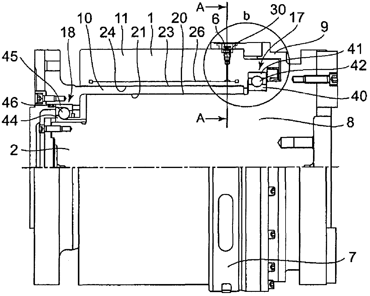
[0051] figure 1 It is an axial schematic diagram of the torque limiter of the first embodiment of the present invention. in figure 1 Among them, the upper half shows an axial cross section of the torque limiter, and the lower half shows a perspective view of the torque limiter.

[0052] The torque limiter includes a cylindrical member 1, a shaft member 2, four shear valves 6, a shear valve protection member 7, a ball bearing 17, and a ball bearing 18.

[0053] The cylindrical member 1 is composed of a first cylindrical member 10 and a second cylindrical member 11. The first cylindrical member 10 has a substantially cylindrical inner peripheral surface 21 that abuts the outer peripheral surface 20 of the shaft member 2. There is an anti-seize lubricant (traction oil or turbine oil) between the outer peripheral surface 20 of the shaft member 2 and the inner peripheral sur...


PUM


Abstract

An annular shear valve protecting member is arranged on an outer circumferential surface of a section extending in a circumferential direction of a cut portion of a shaft member, i.e., at a position outside the shear valve in the diameter direction and in the axis direction same as that of the shear valve. Maintenance or the like of a torque limiter, i.e., replacement of the shear valve or the like, is performed by changing the diameter of the shear valve protecting member by means of an operating section of the shear valve protecting member (7), and suitably switching the state as needed between an urgent state wherein relative movement to the outer circumferential surface of the section extending in the circumferential direction is not permitted, and an urgency-released state wherein movement in the circumferential direction to the outer circumferential surface of the section extending in the circumferential direction is permitted.

Description

Technical field [0001] The invention relates to a torque limiter. Background technique [0002] A conventional type of torque limiter is described in JP-A-62-159815 (Patent Document 1). In this torque limiter, the inner peripheral surface of the cylindrical member is fitted on the outer peripheral surface of the shaft member. Hydraulic oil is supplied into the hydraulic expansion chamber in the cylindrical member. The inner circumferential surface of the cylindrical member is contracted in diameter by the hydraulic oil in the hydraulic expansion chamber, so that the inner circumferential surface is pressed against the outer circumferential surface of the shaft member, thereby frictionally connecting the shaft member and the cylindrical member for torque transmission . In this torque limiter, the cut-off member of the shaft member is locked at the other end of the shear valve communicating with the hydraulic expansion chamber at one end of the shear valve. [0003] When the inne...

Claims


Application Information

Patent Timeline
Patent Type & Authority Applications(China)
IPC IPC(8): F16D7/02F16D1/091
CPCF16D1/0805F16D9/06
Inventor 米山展央永山彰英
Owner JTEKT CORP
Why Eureka
Try Eureka