Vertical rotary workbench of numerical control machine tool

A vertical rotary and CNC machine tool technology, which is applied in the direction of manufacturing tools, metal processing equipment, metal processing machinery parts, etc., can solve the problems that the processing accuracy of the workpiece cannot be guaranteed, the positioning of the rotary table is affected, and the positioning of the workpiece is not accurate enough.

Inactive Publication Date: 2011-05-18
泗洪启航精密机械科技有限公司
View PDF11 Cites 4 Cited by
  • Summary
  • Abstract
  • Description
  • Claims
  • Application Information

AI Technical Summary

Problems solved by technology

The disadvantage of this known vertical rotary table for numerically controlled machine tools is that the rotation and positioning of the rotary table in the circumferential direction depend on the drive of the driving wheel 6' and the driven wheel 7', while the rotation angle of the motor, the driving wheel 6' and the driven wheel 7' will affect the positi

Method used


Image

  • Vertical rotary workbench of numerical control machine tool
  • Vertical rotary workbench of numerical control machine tool
  • Vertical rotary workbench of numerical control machine tool

Examples


Embodiment Construction

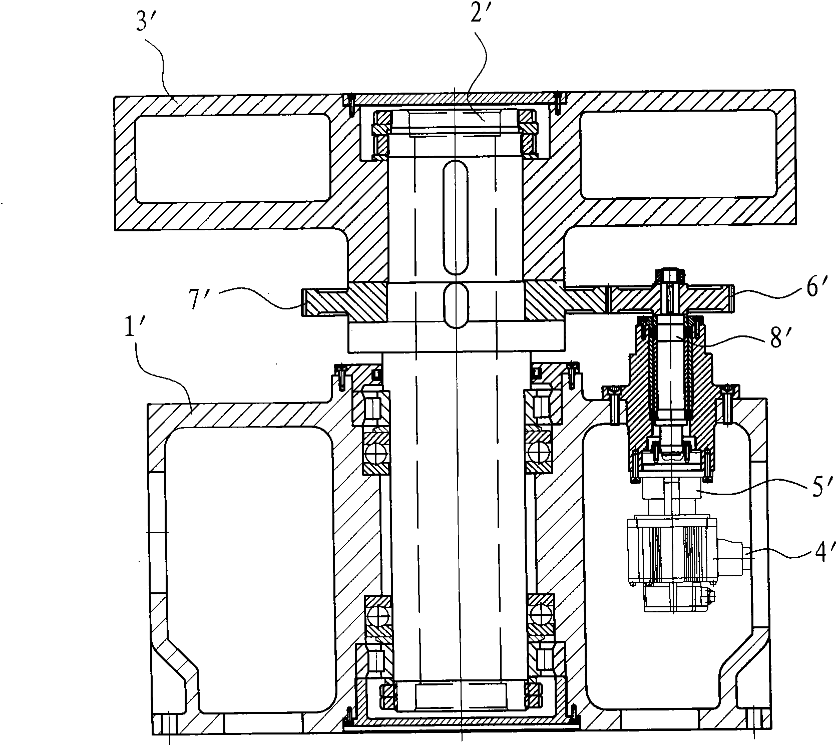
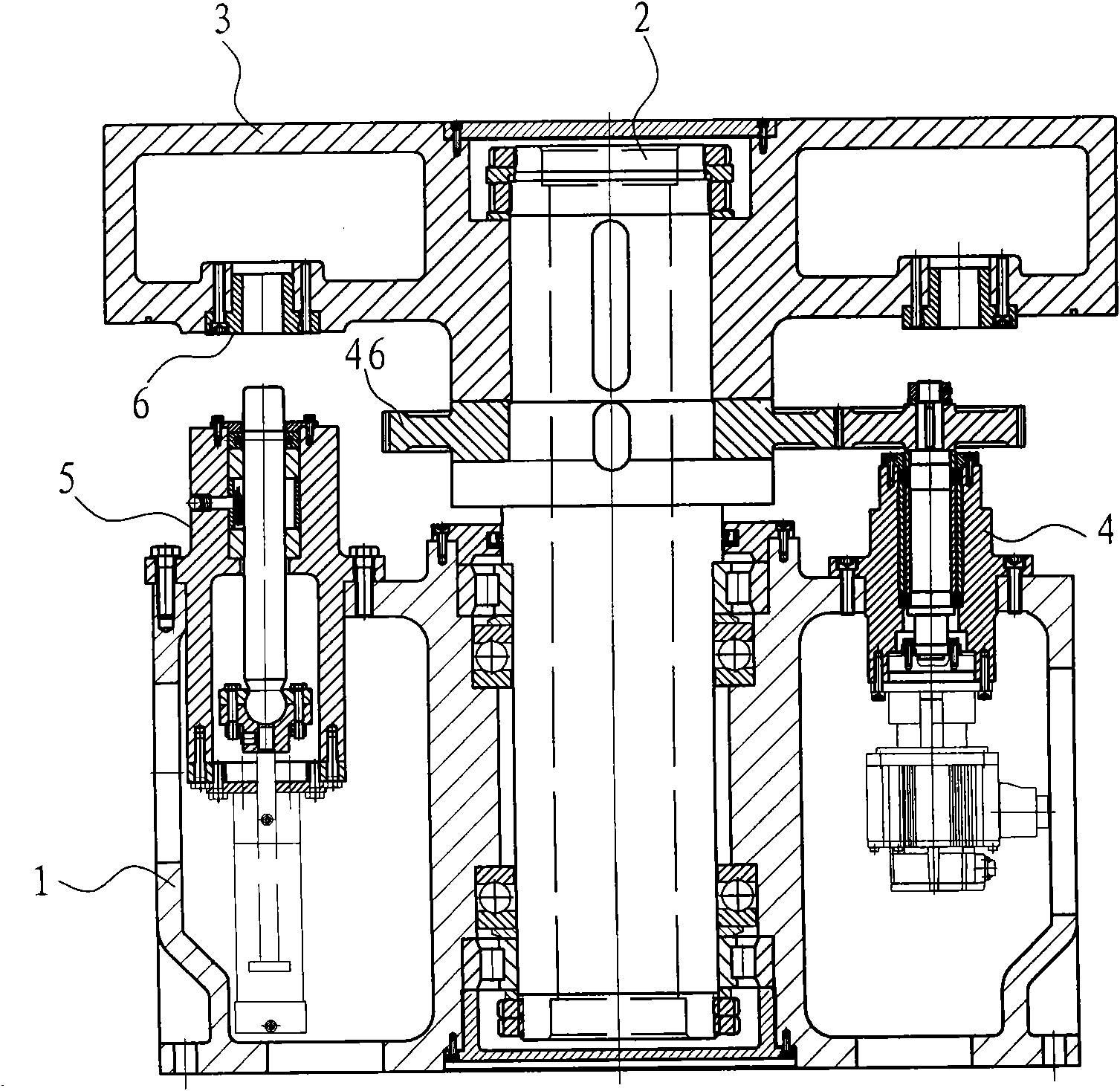
[0014] refer to Figure 2 to Figure 4 , the embodiment discloses a vertical rotary table for a CNC machine tool, which includes a base 1, a rotating shaft 2, a workbench 3, a rotary drive device 4, two indexing positioning devices 5 and four taper pin sleeves 6, wherein:

[0015] The base 1 is used to fix and support other components, the rotating shaft 2 is rotatably arranged vertically on the base 1 through two ball bearings and two roller bearings, and the workbench 3 is fixed on the top of the rotating shaft 2 , Four taper pin sleeves 6 are uniformly arranged on the lower surface of the workbench 3 along the circumferential direction.

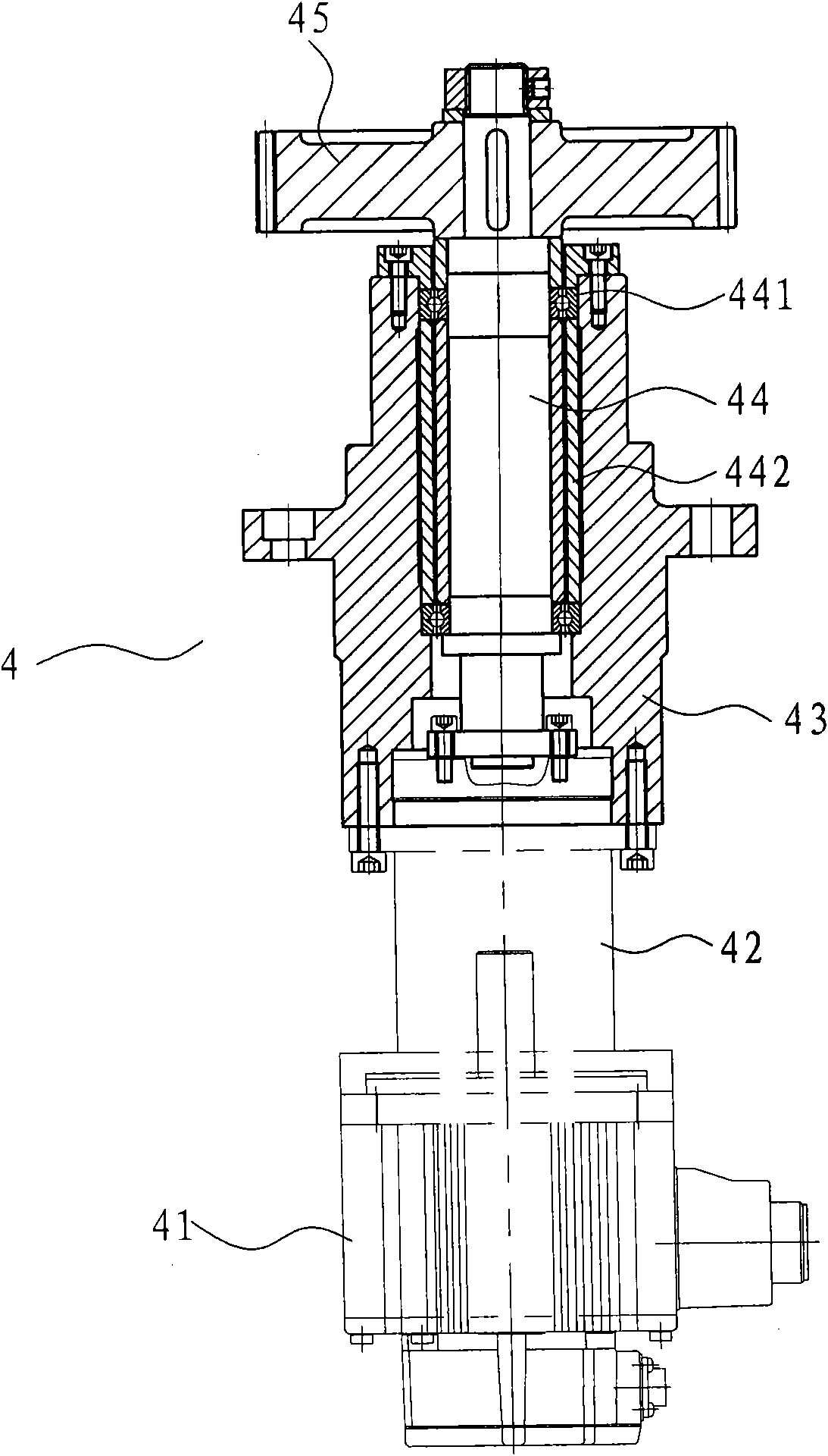
[0016] The rotary driving device 4 is arranged between the base 1 and the rotating shaft 2 to drive the workbench 3 to rotate. The rotary driving device 4 includes a servo motor 41, a reducer 42, a drive shaft fixing seat 43, a drive shaft 44, and a drive shaft. Wheel 45 and driven wheel 46, described driving shaft fixing seat 43 is fixed ...


PUM


Abstract

The invention provides a vertical rotary workbench of a numerical control machine tool with accurate positioning. The vertical rotary workbench comprises a base, a rotating shaft, a workbench and a rotary driving device, wherein the rotating shaft is rotationally arranged on the base; the workbench is fixedly arranged at the top of the rotating shaft; the rotary driving device is arranged betweenthe base and the rotating shaft and used for driving the workbench to rotate; the base is provided with one to four scale division positioning devices; and the lower surface of the workbench is provided with two to eight taper pin sleeves of corresponding scale division angles, and the taper pin sleeves are uniformly distributed along the circumference direction of the workbench.

Description

technical field [0001] The invention relates to a numerical control machine tool, in particular to a vertical rotary workbench of the numerical control machine tool. Background technique [0002] refer to figure 1 , the known vertical rotary table for CNC machine tools generally includes a base 1', a vertical rotary table and a rotary drive device, the base 1' is used to fix and support the vertical rotary table and the rotary drive device, the vertical The rotary table includes a rotating shaft 2' and a table 3', the rotating shaft 2' is rotatably arranged on the base 1' through a bearing, the table 3' is arranged on the top of the rotating shaft 2', and the rotary drive device includes a drive motor 4' reducer 5' drive wheel 6' and driven wheel 7', the drive motor 4' is located on the base 1', the input end of the reducer 5' is connected to the output end of the drive motor 4', the reducer 5 The output end of ' is connected with the driving wheel 6' through the transmiss...

Claims


Application Information

Patent Timeline
IPC IPC(8): B23Q1/26
Inventor 秦士来
Owner 泗洪启航精密机械科技有限公司
Why Eureka
Try Eureka