Multi-purpose loader

A loader, multi-purpose technology, applied in applications, motor vehicles, steering mechanisms, etc., can solve the problems of inconvenient replacement of working devices and delays in working time

Inactive Publication Date: 2011-05-18
HYO CHUN
View PDF7 Cites 7 Cited by
  • Summary
  • Abstract
  • Description
  • Claims
  • Application Information

AI Technical Summary

Problems solved by technology

On the contrary, the prior art has disadvantages that since the working device is detachably attached to the boom assembly by

Method used


Image

  • Multi-purpose loader
  • Multi-purpose loader
  • Multi-purpose loader

Examples


Embodiment Construction

[0022] Hereinafter, a utility loader according to a preferred embodiment of the present invention will be explained in detail with reference to the accompanying drawings.

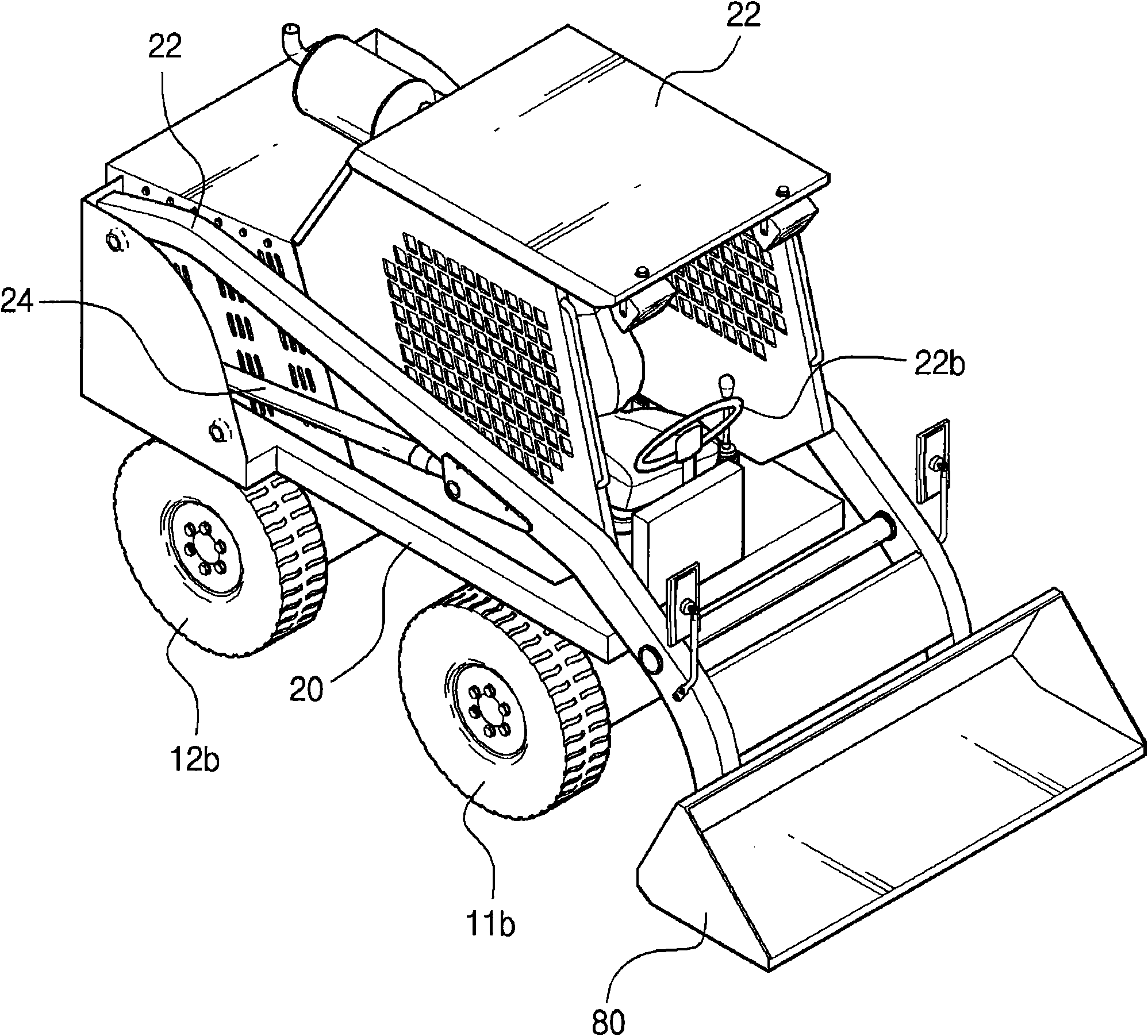
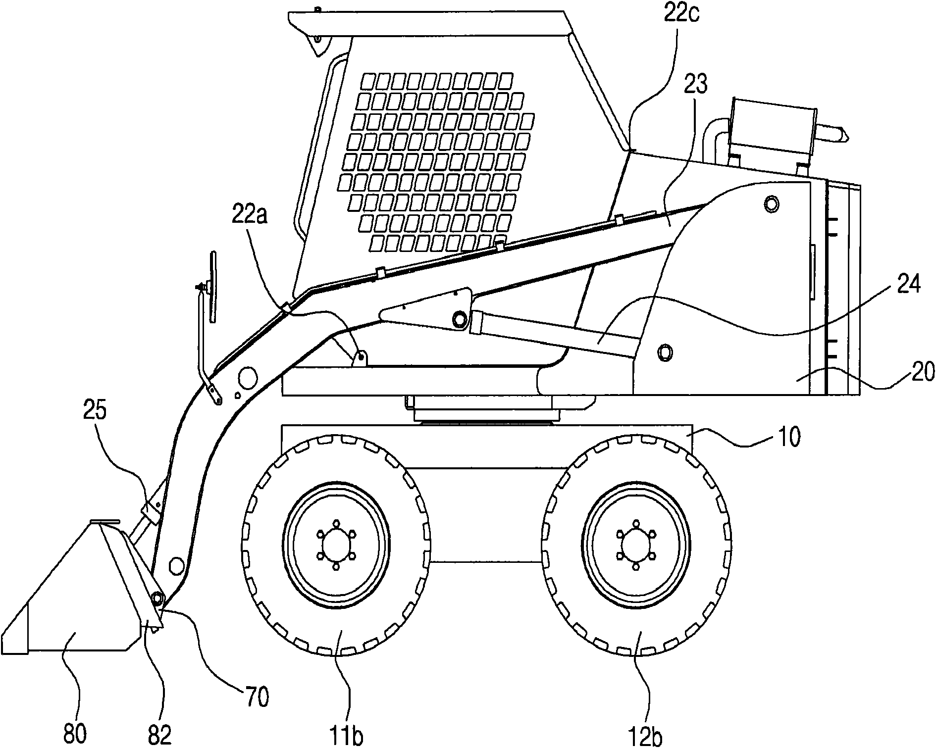
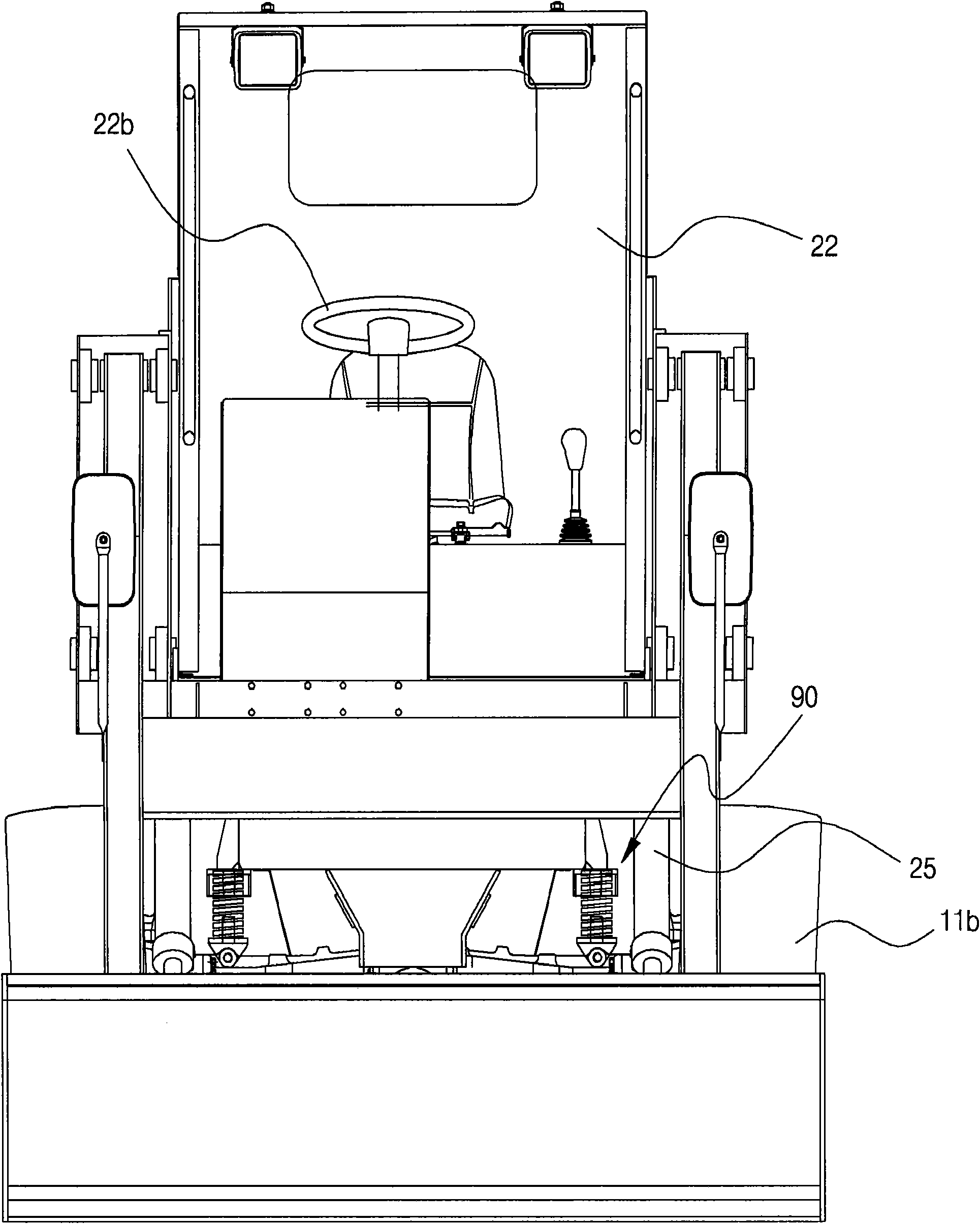
[0023] figure 1 is a perspective view showing a utility loader according to a preferred embodiment of the present invention; figure 2 is showing figure 1 Side view of the utility loader; image 3 is showing figure 1 Front view of the utility loader; Figure 4 is showing figure 1 Bottom view of the utility loader; Figure 5 is showing figure 1 A floor plan of the utility loader; Figure 6 is showing figure 1 The plan view of the lower frame, drive unit, steering unit and coupling unit used in the utility loader of ; Figure 7 is showing Figure 6 A perspective view of the operating state of the drive unit; Figure 8 is shown in figure 1 The bottom view of the state where the lower frame is fixed to the front wheel axle box by the shock absorber in the utility loader of ; Figure 9 is shown in ...


PUM


Abstract

The invention relates to a multi-purpose loader, comprising a lower frame with a front wheel axle box and a rear wheel axle box, an upper frame coupled on the top side of the lower frame and provided with a cab on the top, an upper frame rotating component rotating the upper frame relative to the lower frame, a drive unit driving the front wheels and the rear wheels, a turning unit equipped on the lower frame and rotating the front wheels and the rear wheels according to the rotation of a steering wheel, a linkage unit provided with a linkage body coupled on the two sides of a movable arm equipped on the upper frame and an accessory inserting projecting part formed on the top part of the linkage body, and an accessory provided with an inserting projecting part support groove formed on the upper side of the accessory. Thus the accessory inserting projecting part of the linkage unit is inserted into the accessory in a supporting way.

Description

technical field [0001] The present invention relates to a loader, more particularly to a multi-purpose loader that can be widely used in various fields such as agriculture, animal husbandry, construction and construction. Background technique [0002] In general, industrial vehicles such as loaders are used in relatively narrow spaces to move powdery objects such as soil and sand, to lift objects to stack them to a higher position. [0003] This loader has front wheel and rear wheel and swing arm assembly, and front wheel and rear wheel are arranged on the front and the rear of loader frame lower side, and swing arm assembly is arranged on loader frame upper side place, and in dynamic Attachments such as buckets and forks are detachably mounted on the arm assembly. The loader operates when the boom assembly moves up and down relative to the loader frame. [0004] One of the prior art documents is disclosed in Korean Patent No. 10-0631388 (dated Oct. 4, 2006) entitled "indu...

Claims


Application Information

Patent Timeline
IPC IPC(8): E02F3/96B62D7/00B62D7/16B62D7/18B62D5/06B60G11/14B60B37/00
CPCA01B77/00B60Y2200/415B62D9/00E02F3/34
Inventor 李在律
Owner HYO CHUN
Why Eureka
Try Eureka