
grinding device

A technology of a grinding device and a grinding body, which is applied to grinding devices, grinding machine tools, and devices for fixing grinding wheels, etc., can solve the problems of low replacement operation efficiency, great time and labor consumption, low friction resistance, etc., and achieves shortened maintenance time, The effect of easy replacement work and excellent practicability

Active Publication Date: 2016-06-29
S T LINK
View PDF6 Cites 0 Cited by
  • Summary
  • Abstract
  • Description
  • Claims
  • Application Information

AI Technical Summary

Problems solved by technology

[0003] However, in the grinding process, a load is applied to the rotation of the rotating abrasive body. When the load exceeds the aforementioned frictional resistance, the rotating abrasive body idles. Therefore, if the fastening of the pressing plate is weak, the frictional resistance also decreases accordingly. Small, easy to cause idling and cause failures such as sintering
[0004] Therefore, it is also proposed to have a grinding device (hereinafter referred to as a conventional device) configured to sandwich a rubber plate between the rotating abrasive body and the pressing plate to generate greater frictional resistance, but the rubber plate or the rotating abrasive body are worn due to friction. When the fastening becomes loose, the frictional resistance becomes smaller, causing idling, so it is necessary to periodically reinforce, so that the rubber plate and the pressing plate are firmly pressed against the rotating grinding body, so as to maintain the state where a large frictional resistance is generated. Therefore, in In a conventional device equipped with a plurality of rotating grinding bodies, it takes a lot of time and effort to manage man-hours. In addition, since the bolts are firmly fixed, it is difficult to remove the bolts during replacement, which reduces the efficiency of the replacement work. major factor

Method used


Image

  • grinding device
  • grinding device
  • grinding device

Examples


Embodiment Construction

[0035] The action of the present invention is shown based on the drawings, and preferred embodiments of the present invention will be briefly described.

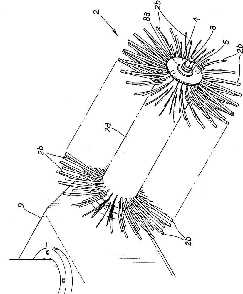
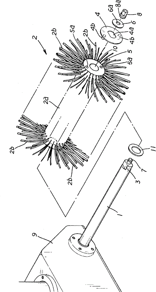
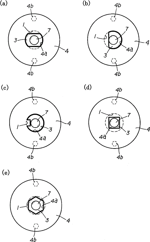
[0036] In the present invention, the anti-rotation fitting part 4 is anti-rotation fitting with the grinding body side fitting part 5 provided on the rotating grinding body 2. On the anti-rotation part 3 that is provided with, therefore do not constitute the structure that the rotating grinding body 2 itself is directly anti-rotation relative to the rotation shaft 1, but is indirectly arranged on the rotation shaft 1 in an anti-rotation state, which can be extremely simple The structure reliably sets the rotating grinding body 2 in a state of being locked relative to the rotating shaft 1 .

[0037] That is, in the case of a structure in which the rotating shaft 1 and the rotating grinding body 2 are directly locked, it is necessary to integrally form the rotating shaft 1 and the rotating grinding body 2, or to make the rotat...


PUM


Abstract

The present invention provides a grinding device, which can arrange a rotating grinding body in a state of rotating together with a rotating shaft by a very simple structure, and can conduct the replacement operation for the rotating grinding body easily. The rotating shaft (1) is provided with a rotating stop part (3). The rotating stop part (3) is provided with a rotating stop embedding part (4) which is embedded in the rotating stop part. The end of the rotating grinding body (2) is provided with a grinding body side embedding part (5) which is embedded with the rotating stop embedding part. The rotating grinding body and the rotating stop embedding part are disposed on the rotating shaft to embed with the rotating stop part and embed with the rotating stop embedding part and the grinding body side embedding part. The rotating stop embedding part stops rotating relative to the rotating shaft, and the grinding body side embedding part is disposed on the end of the rotating grinding body. Thus the rotating grinding body stops rotating relative to the rotating shaft. A locking body (6) is disposed on the end of the rotating shaft in a manner of free assembling. The locking body can prevent the rotating grinding body from dropping from the rotating shaft. So the rotating grinding body is arranged in a manner of free assembling.

Description

technical field [0001] The present invention relates to a grinding device for grinding workpieces to be ground such as metal or wood. Background technique [0002] In the past, in a grinding device in which a rotating grinding body is replaceably provided with a rotating shaft, the rotating grinding body embedded and mounted on the rotating shaft is fastened with bolts via a pressing plate. The frictional resistance generated on the contact surface between the plates makes the rotating grinding body rotate together with respect to the rotating shaft without idling. [0003] However, in the grinding process, a load is applied to the rotation of the rotating abrasive body. When the load exceeds the aforementioned frictional resistance, the rotating abrasive body idles. Therefore, if the fastening of the pressing plate is weak, the frictional resistance also decreases accordingly. If it is small, it is easy to cause idling and become the cause of troubles such as sintering. ...

Claims


Application Information

Patent Timeline
Patent Type & Authority Patents(China)
IPC IPC(8): B24B37/00
CPCB24B41/047B24B45/003B24B45/006
Inventor 宫越惠一斋藤文昭
Owner S T LINK
Learn More