

Lens barrel and lens module using same
A lens module and lens barrel technology, applied in installation, optics, instruments, etc., can solve the problems of wasting colloid and dispensing time, affecting the light transmission area of the lens module, etc., so as to reduce the bonding area and increase the light transmission area. Effect
- Summary
- Abstract
- Description
- Claims
- Application Information
AI Technical Summary
Problems solved by technology
Method used
Image

Examples
Embodiment Construction
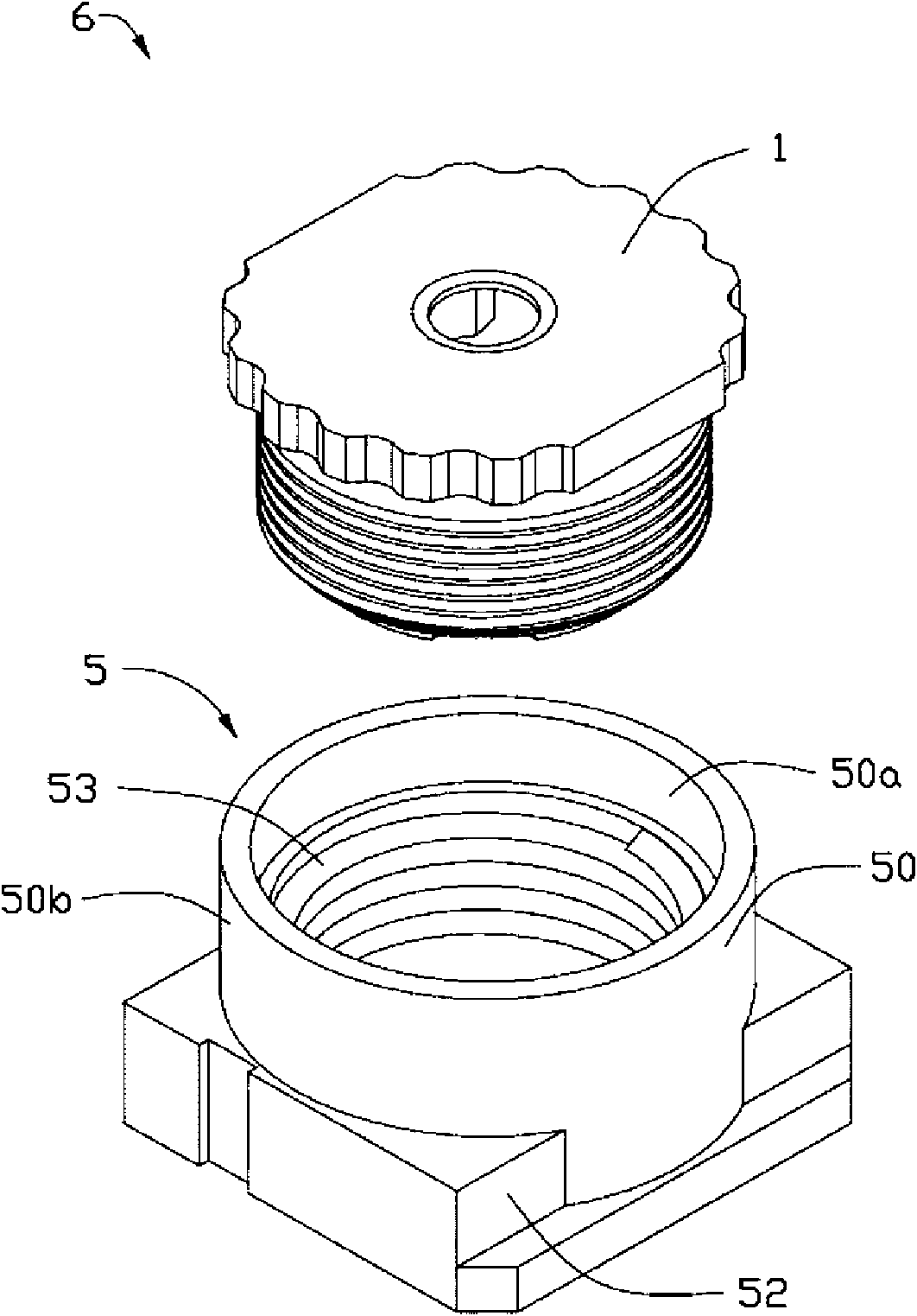
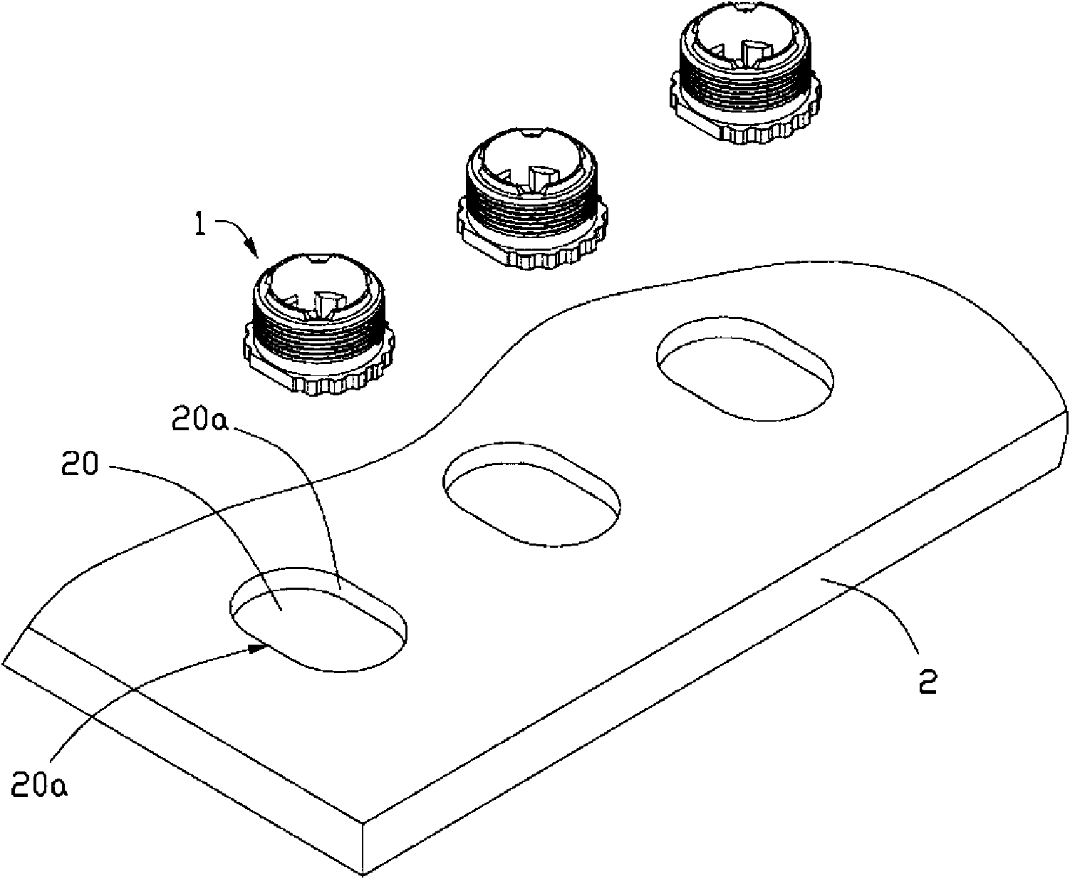
[0012] Such as figure 1 and figure 2 As shown, a lens module 6 provided by an embodiment of the present invention includes a lens barrel 1 and an optical element 3 (see Figure 4 ) and mirror holder 5. The optical element 3 is arranged in the lens barrel 1 , and the lens barrel 1 and the lens base 5 are screwed together.
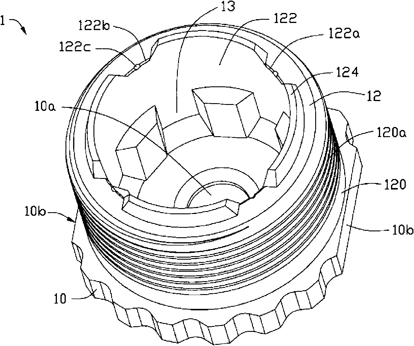
[0013] The lens barrel 1 includes a focus ring 10 and a receiving portion 12 . The receiving portion 12 is a hollow cylinder. A light-transmitting through hole 10a is defined in the center of the focus ring 10 . The focus ring 10 is disposed at one end of the receiving portion 12 and forms a receiving space 13 together with the receiving portion 12 . The axis of the focus ring 10 is aligned with the axis of the receiving portion 12 and passes through the center of the light-transmitting hole 10a.
[0014] The focus ring 10 includes a pair of parallel positioning side surfaces 10b. The receiving portion 12 includes an outer wall 120 and an inner wall ...
PUM
 Abstract
Description
Claims
Application Information