
Optical module

An optical module and optical fiber technology, applied in the field of optical modules, can solve the problems of difficult identification of indicator light modules, small indicator lights, misrecognition of optical modules, etc., to achieve the effect of easy identification, avoid misrecognition, and increase the light transmission area

Active Publication Date: 2018-12-21
HISENSE BROADBAND MULTIMEDIA TECH
View PDF9 Cites 4 Cited by
  • Summary
  • Abstract
  • Description
  • Claims
  • Application Information

AI Technical Summary

Problems solved by technology

[0003] However, in the prior art, since the light-emitting surface of the indicator light is relatively small, and because the optical modules are generally installed in the chassis in batches, when the user is a certain distance away from the chassis, it is difficult for the user to identify the corresponding position of the indicator light. The optical module is identified, which is easy to cause the user to misidentify the optical module

Method used


Image

  • Optical module
  • Optical module
  • Optical module

Examples


Embodiment Construction

[0017] In order to make the object, technical solution and advantages of the present invention more clear, the present invention will be further described in detail below in conjunction with the accompanying drawings and embodiments. It should be understood that the specific embodiments described here are only used to explain the present invention, not to limit the present invention.

[0018] In describing the present invention, it should be understood that the terms "center", "longitudinal", "transverse", "length", "width", "thickness", "upper", "lower", "front", " Orientation indicated by rear, left, right, vertical, horizontal, top, bottom, inside, outside, clockwise, counterclockwise, etc. The positional relationship is based on the orientation or positional relationship shown in the drawings, which is only for the convenience of describing the present invention and simplifying the description, rather than indicating or implying that the referred device or element must hav...


PUM


Abstract

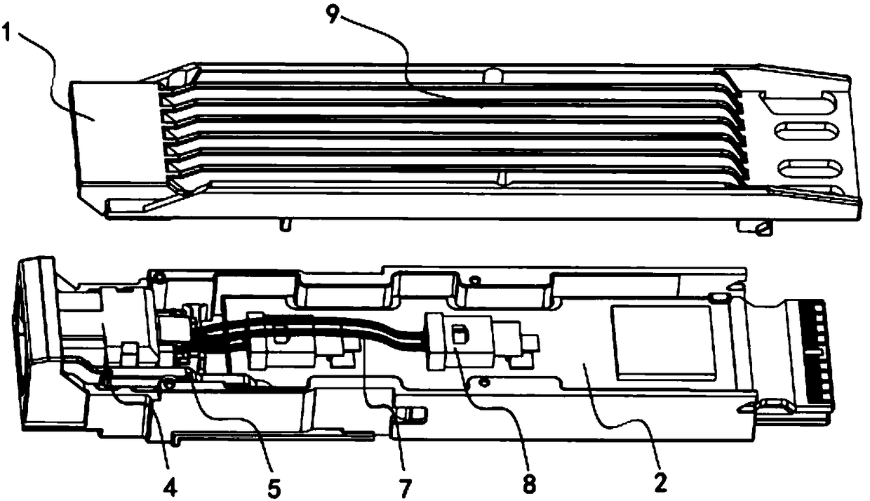
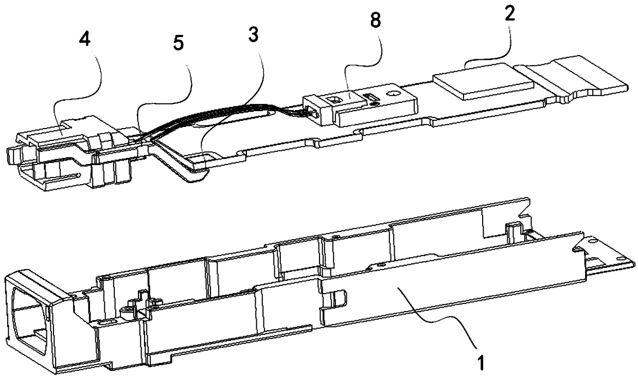
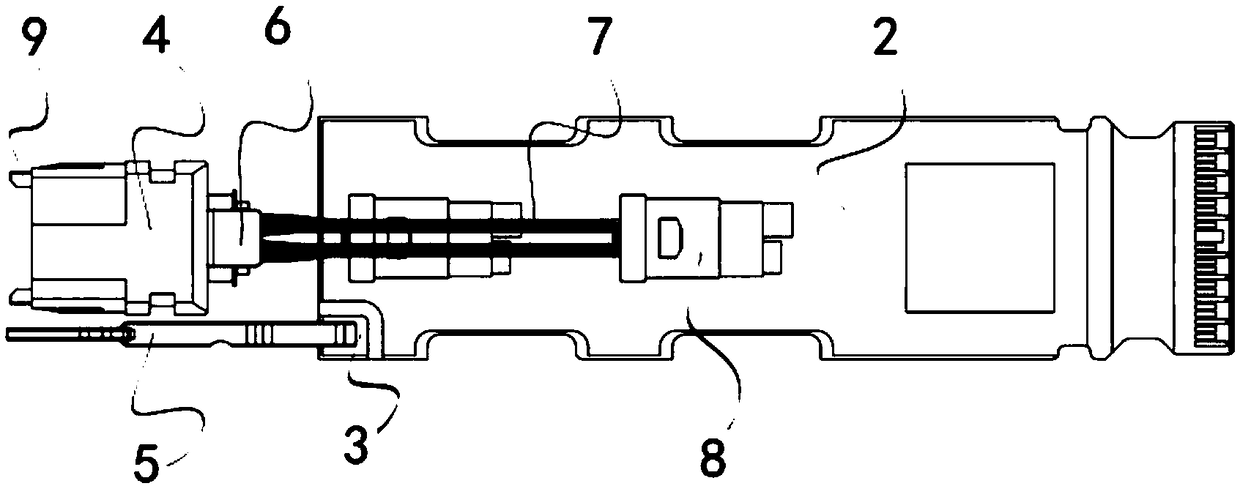
The invention relates to the technical field of optical fiber communication, in particular to an optical module. The optical module comprises an outer shell, wherein a circuit board is installed in the outer shell, and an indicator light is arranged in the circuit board; on end surface of the outer shell is provided with a window through which an optical fiber passes; an optical fiber connector and a light transmission element are arranged in the window; after the optical fiber passes through the light transmission element, the optical fiber is connected with the optical fiber connector; the light transmission element enables light emitted from the indicator light to be transmitted out of the outer shell; and in addition, the area of the light transmission surface of the light transmissionelement on the outer shell is greater than the area of the light emission surface of the indicator light. By use of the optical module, the outer shell of the optical module is provided with the light transmission element, rays emitted from the indicator light penetrate through the light transmission element to be emitted, so that the light transmission area on the outer shell is effectively increased, a user can conveniently identify an indicator light signal in the optical module, and a situation of false recognition is effectively avoided.

Description

technical field [0001] The invention relates to the technical field of optical fiber communication, in particular to an optical module. Background technique [0002] Optical communication is a mainstream communication method nowadays; in the process of existing optical communication, it needs to use optical modules to convert received optical signals into electrical signals. In order to know the working state of the optical module better, an indicator light for displaying the working state of the optical module is provided on the circuit board of the existing optical module. [0003] However, in the prior art, since the light-emitting surface of the indicator light is relatively small, and because the optical modules are generally installed in the chassis in batches, when the user is a certain distance away from the chassis, it is difficult for the user to identify the corresponding position of the indicator light. The optical module is identified, which may easily cause th...

Claims


Application Information

Patent Timeline
Patent Type & Authority Applications(China)
IPC IPC(8): G02B6/42
CPCG02B6/428
Inventor 郑龙
Owner HISENSE BROADBAND MULTIMEDIA TECH
Learn More