Laser radar and laser radar control method

A technology of lidar and control method, applied in the field of detection, can solve problems such as large volume, inability to meet demand, and reduced application

Pending Publication Date: 2017-09-12
SUTENG INNOVATION TECH CO LTD
View PDF8 Cites 3 Cited by
  • Summary
  • Abstract
  • Description
  • Claims
  • Application Information

AI Technical Summary

Problems solved by technology

[0004] If the range of the above-mentioned lidar meets the highest requirements during design, the cost will be higher and the volume may also be larger; if it is designed according to the minimum requirements for the range, it will not be able to meet the high range requirements, which will reduce the user experience and even reduce related ap

Method used


Image

  • Laser radar and laser radar control method
  • Laser radar and laser radar control method
  • Laser radar and laser radar control method

Examples


Embodiment Construction

[0033] The following embodiments of the present invention provide a laser radar and a laser radar control method, which can meet the requirements of high range and low range of the laser radar at the same time.

[0034] The technical solutions in the embodiments of the present invention will be clearly and completely described below in conjunction with the accompanying drawings in the embodiments of the present invention. Obviously, the described embodiments are only some, not all, embodiments of the present invention. Based on the embodiments of the present invention, all other embodiments obtained by persons of ordinary skill in the art without creative efforts fall within the protection scope of the present invention.

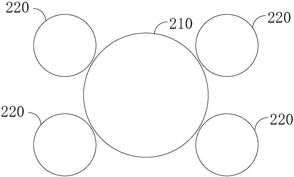
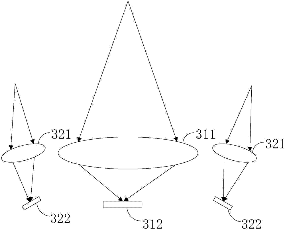
[0035] figure 2 Shown is the schematic diagram of the lidar of the embodiment of the present invention, as figure 2 As shown, the lidar includes two or more groups of collimating units at the receiving end, and the collimating units at the receiving end o...


PUM


Abstract

The embodiment of the invention discloses a laser radar and a laser radar control method. The laser radar comprises two or more two groups of receiving terminal collimation units; and light transmission areas of the receiving terminal collimation units of different groups are different. In addition, according to another embodiment the invention, the invention also discloses a laser radar and a laser radar control method. The laser radar comprises two or more two groups of receiving terminal collimation units; and light transmission areas of the receiving terminal collimation units of different groups are same and the different groups of receiving terminal collimation units correspond to different groups of receiving units. Therefore, requirements of large range and small range of the laser radar can be met. Moreover, the cost is low and the size is small.

Description

technical field [0001] The invention relates to the detection field, in particular to a laser radar and a laser radar control method. Background technique [0002] Lidar is a radar system that emits laser beams to detect the position, speed and other characteristic quantities of the target. Its working principle is to first transmit the detection laser beam to the target, and then compare the received signal reflected from the target with the transmitted signal. After proper processing, the relevant information of the target can be obtained, such as target distance, azimuth, height, speed, attitude, and even shape and other parameters. [0003] In the application of lidar, there may be different range requirements for different azimuth angles, such as lidar installed on cars. figure 1 Shown is a schematic diagram of the range requirements for a LiDAR mounted on an automobile. The obstacles directly in front of the car have the greatest impact on the driving of the car, so ...

Claims


Application Information

Patent Timeline
IPC IPC(8): G01S17/02
CPCG01S17/02
Inventor 邱纯鑫刘乐天
Owner SUTENG INNOVATION TECH CO LTD
Why Eureka
Try Eureka