Method for changing a roller in a roll mill for a continuously running steel strip

A technology of traveling direction and rolling mill, applied in the direction of metal rolling stand, metal rolling mill stand, rolling force/roll gap control, etc., can solve the problems of aggravation, incorrect control of replacement operation, etc., and achieve time sequence simplification, Effect of good scrap recycling, time sequence reduction

Inactive Publication Date: 2011-05-18
PRIMETALS TECH FRANCE
View PDF2 Cites 4 Cited by
  • Summary
  • Abstract
  • Description
  • Claims
  • Application Information

AI Technical Summary

Problems solved by technology

Systematizing the passage of the strip weld and the change of the rolls in such a way inevitably leads to its simultaneous occurrence with all changes in the strip specification, exacerbating the risk of not properly controlling the change operation, whatever the strip

Method used


Image

  • Method for changing a roller in a roll mill for a continuously running steel strip
  • Method for changing a roller in a roll mill for a continuously running steel strip
  • Method for changing a roller in a roll mill for a continuously running steel strip

Examples


Embodiment Construction

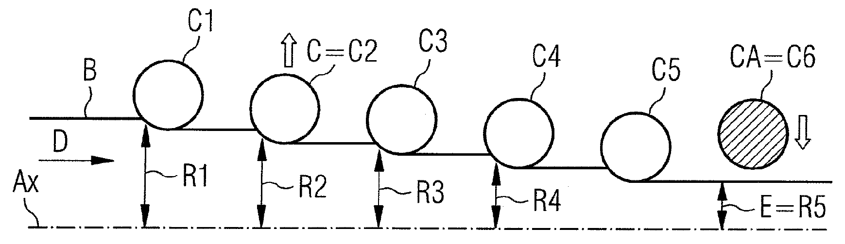
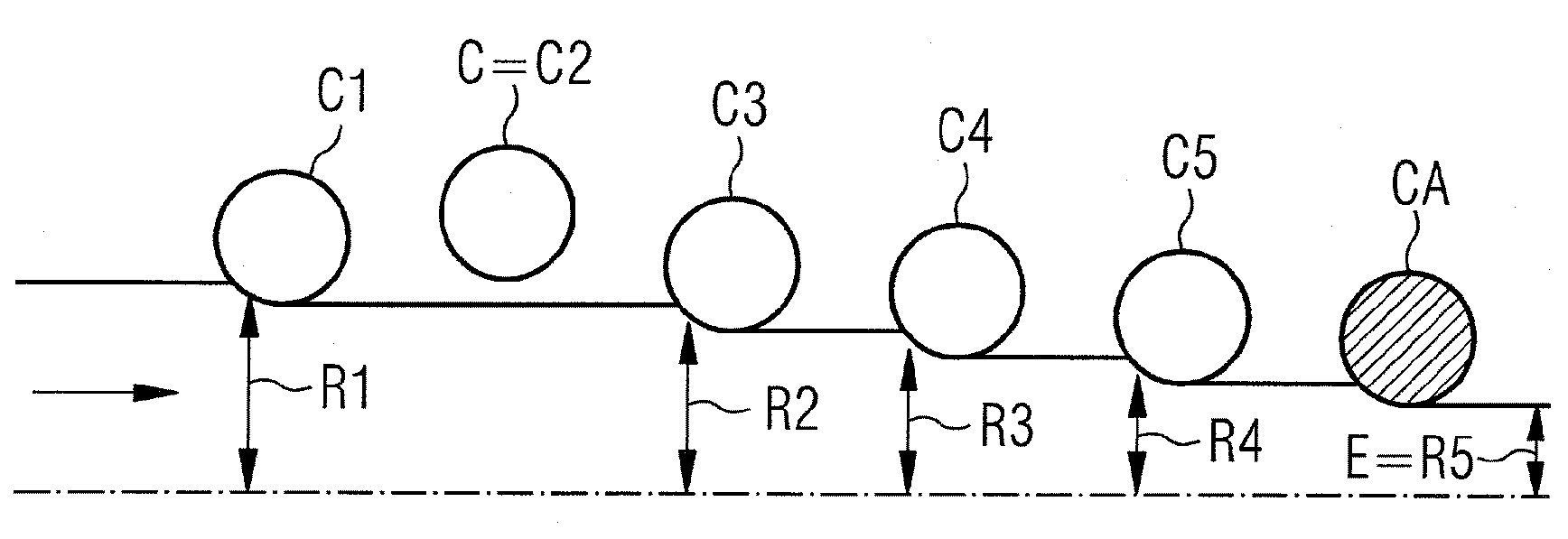
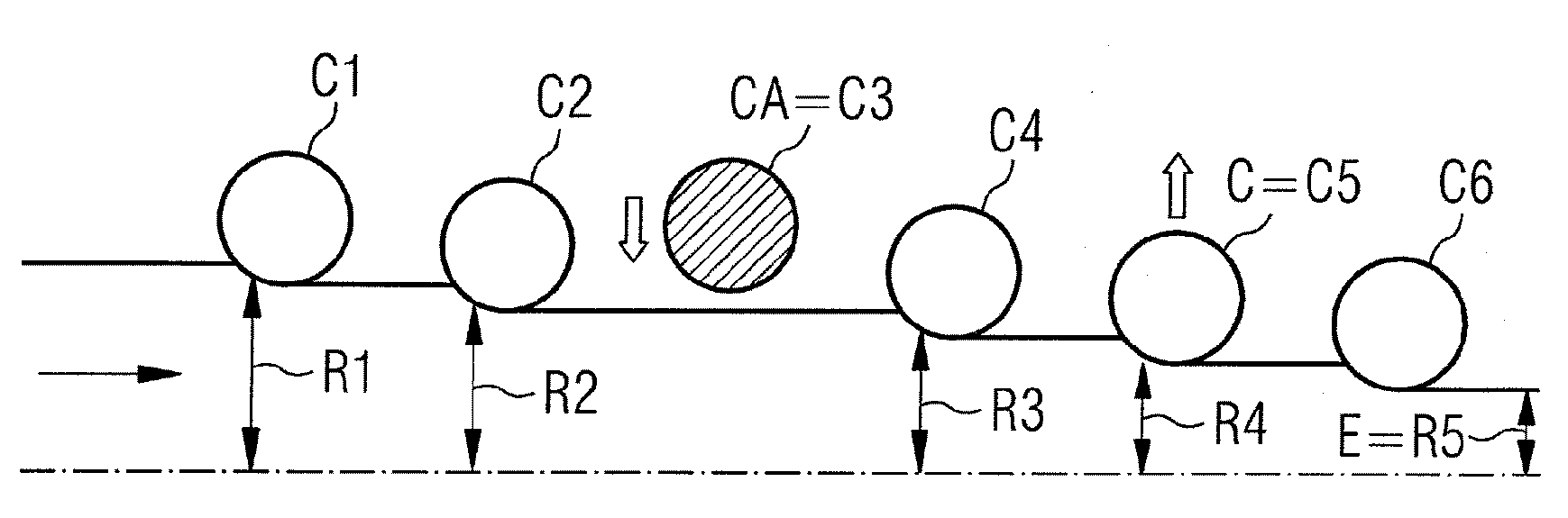
[0044] All the figures described below show a rolling mill comprising six stands and their rolls C1 , C2 , C3 , C4 , C5 , C6 arranged one behind the other in the direction D of their travel along the continuously running strip B. For the sake of clarity, the upper section of the strip, interrupted by the plane of symmetry Ax (parallel and equidistant to the two surfaces of the strip) is also shown. A clamp command value R1, R2, R3, R4, R5 is assigned to each of the five rolls in the rolling working position among the six rolls. By extension, the term "frame" will be used to denote at least one roller in the frame. Likewise, the terms "first rack", "second rack" ... "Nth rack" will be used. This number indicates that the first stand is located furthest upstream in the direction D of strip travel (at the strip entry to the rolling mill), while subsequent stands are placed more and more downstream of the first stand.

[0045] More generally, the rolling mill shown allows implem...


PUM


Abstract

The invention relates to a method for changing rollers in a roll stand (C) adapted for bearing at least one working roller for a continuously-running steel-strip roll mill, wherein said stand (C) is part of a plurality (N) of roll stands arranged in series along the roll mill in the continuous running direction (D), wherein a rolling standby function in a free clamping position of the roller (s) is allocated to at least one dedicated stand (CA) among the plurality (N) of stands, origin setpoint values controlling an adjustment of the roller clamping are individually allocated to the other stands in an active rolling position, and in the case of a roller change when passing into the free clamping position of the cage (C), the origin setpoint value of said cage (C) and the origin setpoint values of the cages remaining in an active rolling position are redistributed individually among each of said cages, including the dedicated cage (CA).

Description

technical field [0001] The invention relates to a method of changing rolls in a rolling mill for a continuously traveling steel strip as stated in the preamble of claim 1 . [0002] In particular, the present invention relates to the technical field of cold rolling steel strips on continuous rolling mills of the tandem type, which require replacement of rolls. Background technique [0003] Cold rolling of steel strip can be carried out on different types of rolling equipment: [0004] - so-called "reversing" rolling plants, in which the strip to be rolled alternates between at least two elements capable of indiscriminately ensuring the unwinding and recoiling of the strip during the individual rolling passes Travel in one direction of travel and then in the other direction of travel. Between these unwinding / coiling sections, the strip is rolled in a single rolling stand, which provides the plant with a production capacity of 200,000 to 600,000 tons / year, or in two rolling...

Claims


Application Information

Patent Timeline
Patent Type & Authority Applications(China)
IPC IPC(8): B21B31/08
CPCB21B37/58B21B31/08B21B1/24B21B2271/02B21B2013/003B21B2265/14Y10T29/4973
Inventor V·克罗尼耶B·罗西尼厄
Owner PRIMETALS TECH FRANCE
Why Eureka
Try Eureka