Permanent magnet rotor, and rotating machine comprising such a rotor

A technology of permanent magnets and rotors, applied in the direction of magnetic circuit rotating parts, magnetic circuits, electromechanical devices, etc., can solve problems such as limiting the power of magnets

Inactive Publication Date: 2011-05-18
MOTEURS LEROY SOMER
View PDF10 Cites 18 Cited by
  • Summary
  • Abstract
  • Description
  • Claims
  • Application Information

AI Technical Summary

Problems solved by technology

This angular overlap between the housing for the magnet and the slot necessitates that the magnet be spaced from the channel for the shaft, which limits the magnet power suitable for use in a rotor of a given size

Method used


Image

  • Permanent magnet rotor, and rotating machine comprising such a rotor
  • Permanent magnet rotor, and rotating machine comprising such a rotor
  • Permanent magnet rotor, and rotating machine comprising such a rotor

Examples


Embodiment Construction

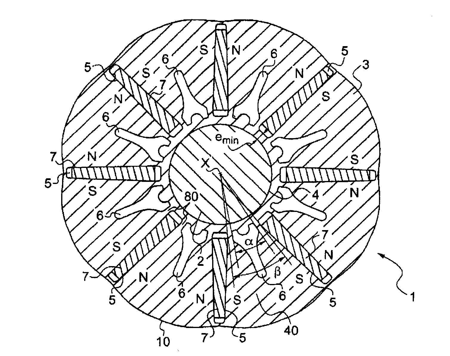
[0071] figure 1 The rotor 1 shown comprises a magnetic rotor mass 3 extending axially along the axis of rotation X of the rotor, for example formed by a stack of laminations stacked along the axis X, said laminations being for example all identical and are precisely stacked together.

[0072] The rotor 1 has a plurality of permanent magnets 7 arranged in corresponding accommodations in the magnetic rotor mass, such that two consecutive magnets 7 have the same magnetic poles on their facing faces.

[0073] A rotor mass 3 is mounted on a shaft 2 which, in the described embodiment, is made of a magnetic material such as steel.

[0074] The rotor mass 3 has a central opening 4 for receiving the shaft 2 .

[0075] The rotor 1 is housed in a stator (not shown) comprising, for example, windings which may be concentrated or dispersed. When used as a synchronous motor, the stator is used to generate a rotating magnetic field that drives the rotor to rotate, and when used as an alter...


PUM


Abstract

The present invention relates to a rotor (1) for rotating an electric machine having permanent magnets (7) and flux concentration, comprising: a shaft (2) extending along the rotational axis (X) of the rotor (1), a rotor body (3) placed on the shaft (2), the rotor body (3) comprising: - a central opening (4) for the mounting thereof on the shaft (2); - radially oriented recesses (5) wherein the permanent magnets (7) are placed; and in at least one angular space (40) separating two consecutive recesses (5), at least one cavity (6) leading neither to the central opening (4) nor to the two consecutive recesses (5), said cavity or cavities (6) located in said space occupying an angular area (a) around the rotational axis (X) of the rotor (1) greater than or equal to half of the angular area (ss) of said space (40).

Description

technical field [0001] The present invention relates to a rotary electric machine, in particular to a synchronous electric machine, and more particularly to a machine having a rotor with permanent magnets and capable of concentration de flux. Background technique [0002] A rotor with a dense magnetic flux comprises a rotor mass in which magnets are accommodated, the magnets engaging in radially oriented receptacles. [0003] The advantage of this type of rotor is that you can get an average inductance in the air gap that is greater than the working inductance of the magnets, so you can reduce the cost of the machine by using ferrite based magnets, or you can make the machine more compact by using rare earth based magnets. [0004] Flux losses in the rotor must be reduced and the flux of the permanent magnets must be looped through the stator rather than through the rotor or rotor shaft. [0005] To this end, several solutions are known, but each has several disadvantages. ...

Claims


Application Information

Patent Timeline
Patent Type & Authority Applications(China)
IPC IPC(8): H02K1/27
CPCH02K1/2773
Inventor 多米尼克·肯德明米歇尔·拉伯尼帕特里克·卡慕斯斯特凡·杜法
Owner MOTEURS LEROY SOMER
Why Eureka
Try Eureka