Nozzle plate of color sorter
A nozzle plate and color sorter technology, applied in the field of color sorters, can solve problems such as unsmooth air flow, affecting production stability, unreasonable design, etc., and achieve the effect of improving efficiency
Inactive Publication Date: 2011-05-25
ANHUI JIEXUN OPTOELECTRONICS TECH
View PDF6 Cites 1 Cited by
- Summary
- Abstract
- Description
- Claims
- Application Information
AI Technical Summary
Problems solved by technology
The nozzle is the main working part of the color sorter. The air intake of the original nozzle needs to be turned 90° and then ejected from the nozzle. Due to the structural limitation of the machine, the air inlet can only enter from the lower part, so the design is not reasonable enough, resulting in unsmooth air flow. Affect the stability of production
Method used
View moreImage
Smart ImageViewing Examples
Examples
Embodiment Construction
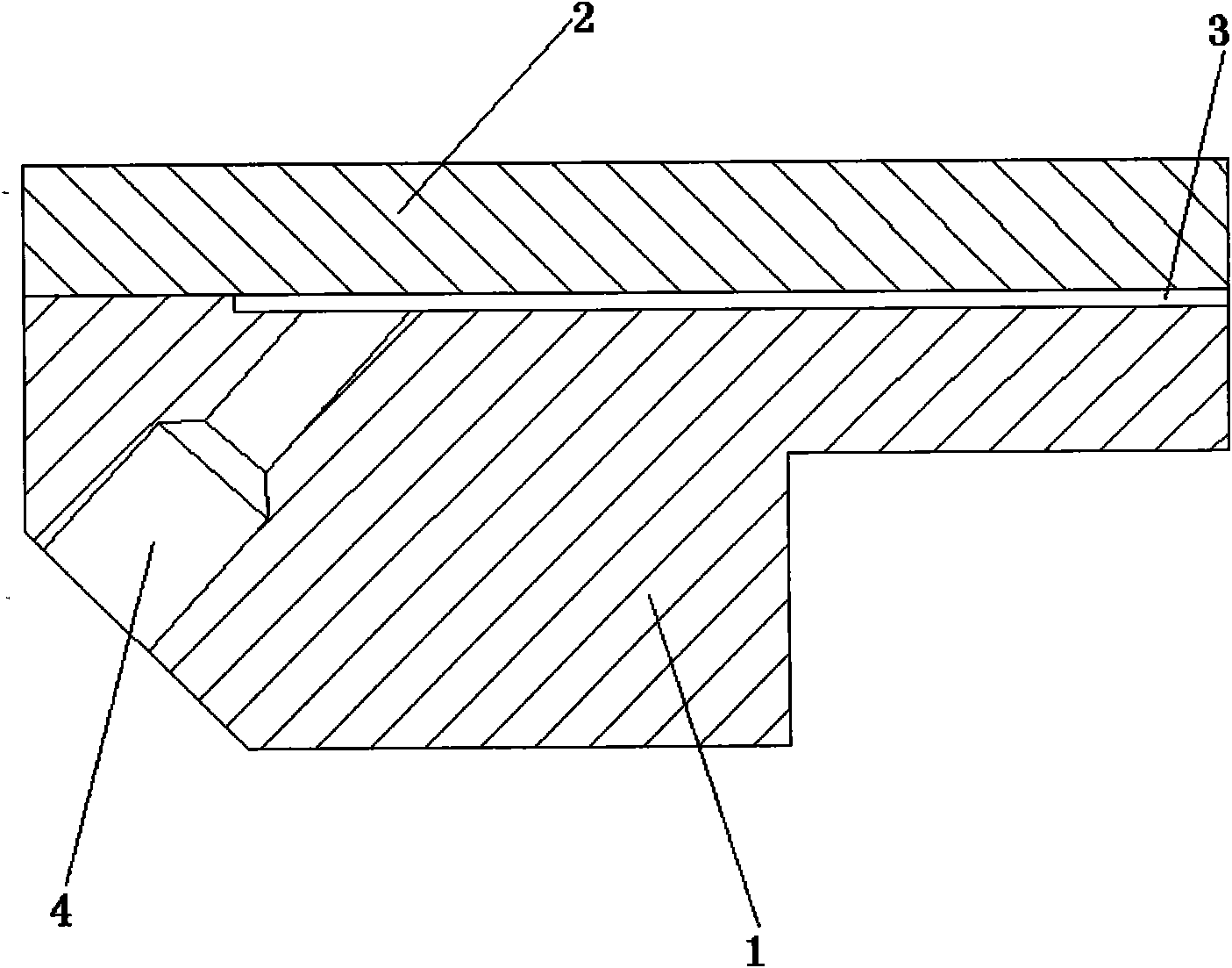
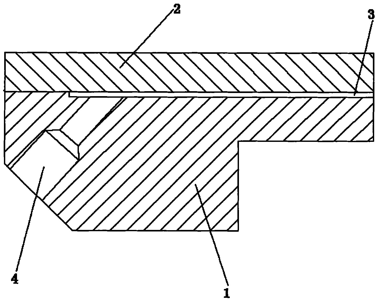
[0009] Referring to the accompanying drawings, the nozzle plate of the color sorter includes a nozzle plate body 1 and a nozzle cover 2. The gap between the nozzle plate body 1 and the nozzle cover 2 is the nozzle opening 3, and there are multiple inclined inlets in the nozzle plate body. Air port 4, the end of air inlet 4 communicates with nozzle port 3, and the inclination angle of air inlet 4 is 52 °.
Login to View More PUM
| Property | Measurement | Unit |
|---|---|---|
| Slope | aaaaa | aaaaa |
Abstract
The invention discloses a nozzle plate of a color sorter, which comprises a nozzle plate body and a nozzle cover, wherein a gap between the nozzle plate body and the nozzle cover is a nozzle exit, the inside of the nozzle plate body is provided with a plurality of inclined air inlets, and the tail s of the air inlets are communicated with the nozzle exit. The nozzle plate disclosed by the invention has the advantages that because a 52-degree included angle is formed between the air inlets and a horizontal line, the gas injection is smoother, and to airflows with an injection time of three-thousandths seconds, the structures of airflow channels are extremely sensitive, thereby improving the production efficiency.
Description
technical field [0001] The invention relates to the technical field of color sorters, in particular to the nozzle plate of the color sorter. Background technique [0002] Color sorter is an effective sorting equipment used for quality testing and grading of bulk materials. It is widely used in grain, food, pigment chemical industry and other industries. According to the difference in the optical characteristics of the material, the equipment that uses photoelectric technology to automatically sort out the heterochromatic particles in the granular material. The nozzle is the main working part of the color sorter. The air intake of the original nozzle needs to be turned 90° and then ejected from the nozzle. Due to the structural limitation of the machine, the air inlet can only enter from the lower part, so the design is not reasonable enough, causing the airflow to be blocked. affect the stability of production. Contents of the invention [0003] The object of the present...
Claims
Login to View More Application Information
Patent Timeline
 IPC IPC(8): B07C5/342
Inventor 高小荣王志平卢萍
Owner ANHUI JIEXUN OPTOELECTRONICS TECH
Features
- R&D
- Intellectual Property
- Life Sciences
- Materials
- Tech Scout
- Unparalleled Data Quality
- Higher Quality Content
- 60% Fewer Hallucinations
Learn More Browse by: Latest US Patents, China's latest patents, Technical Efficacy Thesaurus, Application Domain, Technology Topic, Popular Technical Reports.
© 2025 PatSnap. All rights reserved.Legal|Privacy policy|Modern Slavery Act Transparency Statement|Sitemap|About US| Contact US: help@patsnap.com


